Hello,
We have a 400Hz application using UCC28180. Overall, it's been easy to use, but we are having some difficulties improving the current distortion and harmonic content at about the 15th harmonic. The standard we are attempting to comply with requires testing with a non-sinusoidal input voltage wave-shape. This is to test whether the equipment can still maintain good current-distortion even when the voltage is heavily distorted. With a 0% THD sine wave, the current harmonics are great, very low ITHD. But, with about ~8% VTHD, the ITHD at ~15th harmonic (6KHz) is not so great. We are wondering if maybe the current loop is oscillating causing a 6KHz component on the input current wave. Is it reasonable? Possible?
Of course, with a distorted input voltage, you cannot expect that the input current will not be distorted. So, the standard basically the current harmonics limits are "added" to the actual voltage distortion in each harmonic. This is already accounted for.
The bulk of the issue was actually improved by reducing the total input capacitance in the input filter...which causes distortion due to abrupt change in voltage (dv/dt) with distorted (clipped) input voltage.
But, we still need to improve the distortion.
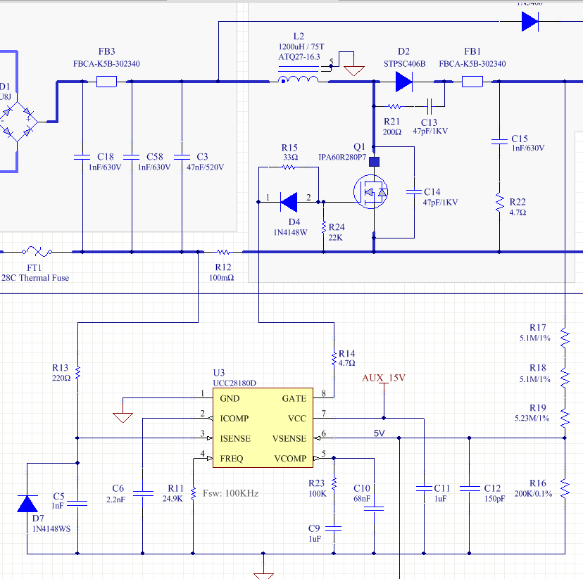
We noted in SLUUAT3B (UCC28180EVM), an R and C are left unpopulated across ICOMP. In a typical compensation network, this converts a 'C only' Type-I network into Type-II. This adds phase boost and increases mid-band gain. Can anyone advise what frequency the zero should be set to? The BOM shows 100R + 0.1uF, which sets fz1 = 15.9KHz. If we have issues around 6KHz, should this be set lower? For instsance, 150R + 0.22uF = 4.8KHz.
What does this network hypothetically help with? Any ideas how how to approach?
Thanks,
Tim