This thread has been locked.

If you have a related question, please click the "Ask a related question" button in the top right corner. The newly created question will be automatically linked to this question.

BQ24640: mosfet driver PWM reaching only 2V

Part Number: BQ24640

Hi TI,

I have been trying to build a basic BQ24640 charger for a single 2.7V 330F supercap. I am trying to reach the advertised 10A charging current. My circuit replicates the circuit from the eval board https://www.ti.com/tool/BQ24640EVM. The experiment uses the power mosfets SIR460DP (https://www.mouser.com/datasheet/2/427/sir460dp-93818.pdf), a high current 3.3uH inductor, and otherwise follows the eval board.

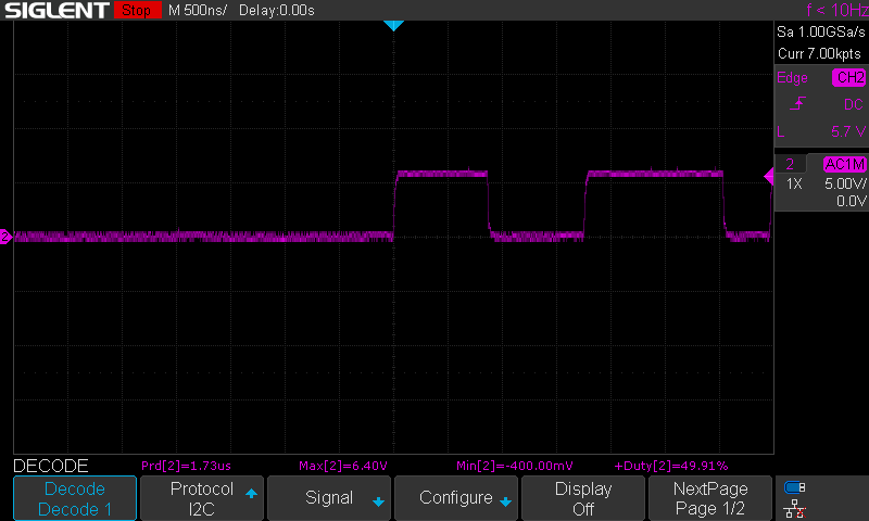
As I am debugging I noticed that the gate source voltage PWM on the mosfets swings between 2.1V for high and 0V for low. The frequency is correct and the REGN pin shows 6V. It is my understanding, that the drivers should be driving with 6V and not 2V? I am wondering where the problem might be? Am I correct in seeing this as the problem for why the circuit never reaches 10A?

Best, Julian

  • Julian,

    Your understanding is correct. LODRV should be 6V for HIGH and 0V for LOW. HIDRV should be 6V + V_PH for HIGH and V_PH for LOW.

    About your MOSFETs, The SIR460DP you selected have significantly more gate charge than the recommended SiR426DP. 16.8 nC versus 9.3 nC. Are you also seeing this abnormal behaviour with the SiR426DP?

    Thanks,

    Ricardo

  • Hi Ricardo,

    Thanks for confirming.

    I have not tried the SiR426DP but I have tried the SiS412DN which has a gate charge of 3.8nC (if I read the datasheet right https://www.mouser.com/datasheet/2/427/sis412dn-1765088.pdf). I am seeing the same 2.1V HIGH drive signal for the SiS412DN unfortunately. If I am thinking about not being able to charge the gate of the MOSFETs fully to 6V, the only other thing that could be it is the connection from IC to gate, right? On my PCB the trace to the MOSFET gate connection in both cases is a simple 0.254mm wide trace with two vias each. Would that be a problem?

    Best, Julian

  • Julian,

    Could you capture an oscilloscope shot of PH, HIDRV, and LODRV during operation?

    Thanks,

    Ricardo

  • Hi Ricardo,

    As I was measuring the signals again, I realized, that the probe I was using was set to 10x but the oscilloscope was not! That is likely why I was not seeing anything reasonable. After fixing that I now get precisely what I should be getting and the world makes sense again :)! HiDrv is 6V above PH and LoDrv is 6V above GND as expected. See below.

    One last question: LoDrv is only enabled towards the end of the charge cycle (around 2V?). From the datasheet it sounds like this is due to nonsynchronous mode below 2V capacitor voltage. When charging a single supercap, that is most of the charging operation. It seems that during nonsynchronous mode, the low side MOSFET heats up way more quickly than the high side one. Is this due to energy losses in the body diode? Can this be mitigated? Should I parallel the body diode with a schottky diode?

    And just to double check: independent of synchonous or nonsynchonous operation I should expect the charger to charge at the desired current? I.e. Fig 8 in the BQ datasheet is valid even in the sub 2V supercapacitor region?

    Below the readouts: Hi Drive, PH, Low Drive:

  • Hi Julian,

       You are correct. During the non synchronous mode the LSFET is conducting through its body diode, and the FET itself is not turned on. This is for low charge currents to prevent negative inductor current. The increased LSFET heat is due to the power dissipation across the LSFET. You are also correct that reducing the forward voltage drop of the LSFET body diode, by adding a schottky diode in parallel will help with efficiency and lower the thermal dissipation.

    Yes, with regards to charge current, you can refer to the EC table to observe the charge current limits. 

  • Julian,

    A parallel schottky diode should help reduce some of the heat. I think this is a good next step.

    Best Regards,

    Ricardo

  • Thanks Ricardo and Kedar for all the help so far!

    Would you mind clarifying the question: independent of synchonous or nonsynchonous operation I should expect the charger to charge at the desired current? I.e. Fig 8 in the BQ datasheet is valid even in the sub 2V supercapacitor region?

    Kedar I am not sure which table you are referring to?

    Best, Julian

  • Julian,

    Would you mind clarifying the question: independent of synchonous or nonsynchonous operation I should expect the charger to charge at the desired current? I.e. Fig 8 in the BQ datasheet is valid even in the sub 2V supercapacitor region?

    Your understanding is correct as long as sufficient power is available and the Electrical Characteristics Table "EC Table" is respected.

    Best Regards,

    Ricardo

  • Great thank you Ricardo!