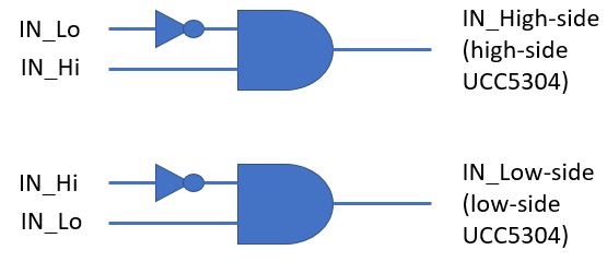
How do I implement interlock protection using the UCC5304 in half-bridge applications?

-
Ask a related question
What is a related question?A related question is a question created from another question. When the related question is created, it will be automatically linked to the original question.