Hi,
I have following queries on TPS7A53-Q1
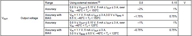
1)In the datasheet pg no:6, accuracy of output voltage is provided.
a)What is accuracy with Bias? Is it when bias voltage is used
b)In the accuracy with Bias for 125C Junction, -0.75% and 75% is provided. Whether this -0.75% and 0.75% is the accuracy of internal reference voltage(0.8V)? If not, what is the variation of 0.8V?
2)When the input voltage is above 3.3V, is it ok to use bias voltage?
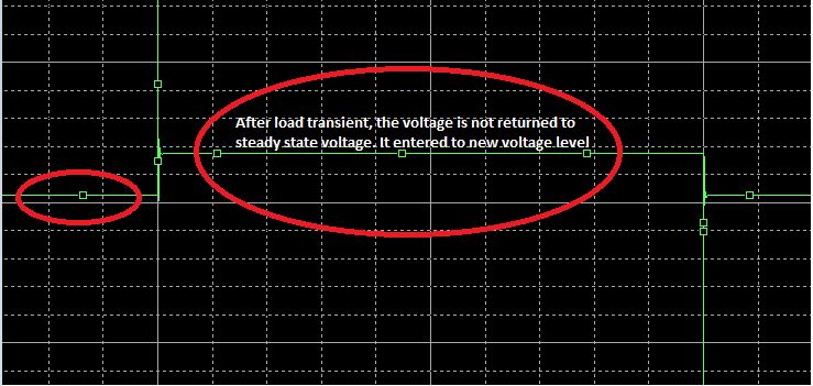
3)What is the maximum limit of soft -start voltage? When simulated using the Pspice model, it is found that the voltage on SS pin capacitor keeps on increasing.
4)Whether using 12.7kohm resistor instead of 12.1kohm resistor will cause any problem?
Please resolve the issue
Thanks
Viswa