This thread has been locked.

If you have a related question, please click the "Ask a related question" button in the top right corner. The newly created question will be automatically linked to this question.

LM25066: LM25066 current limit setting

Part Number: LM25066

Hi team,

According to the datasheet, current limit threshold can be set to 25mV when CL pin is connected to GND.

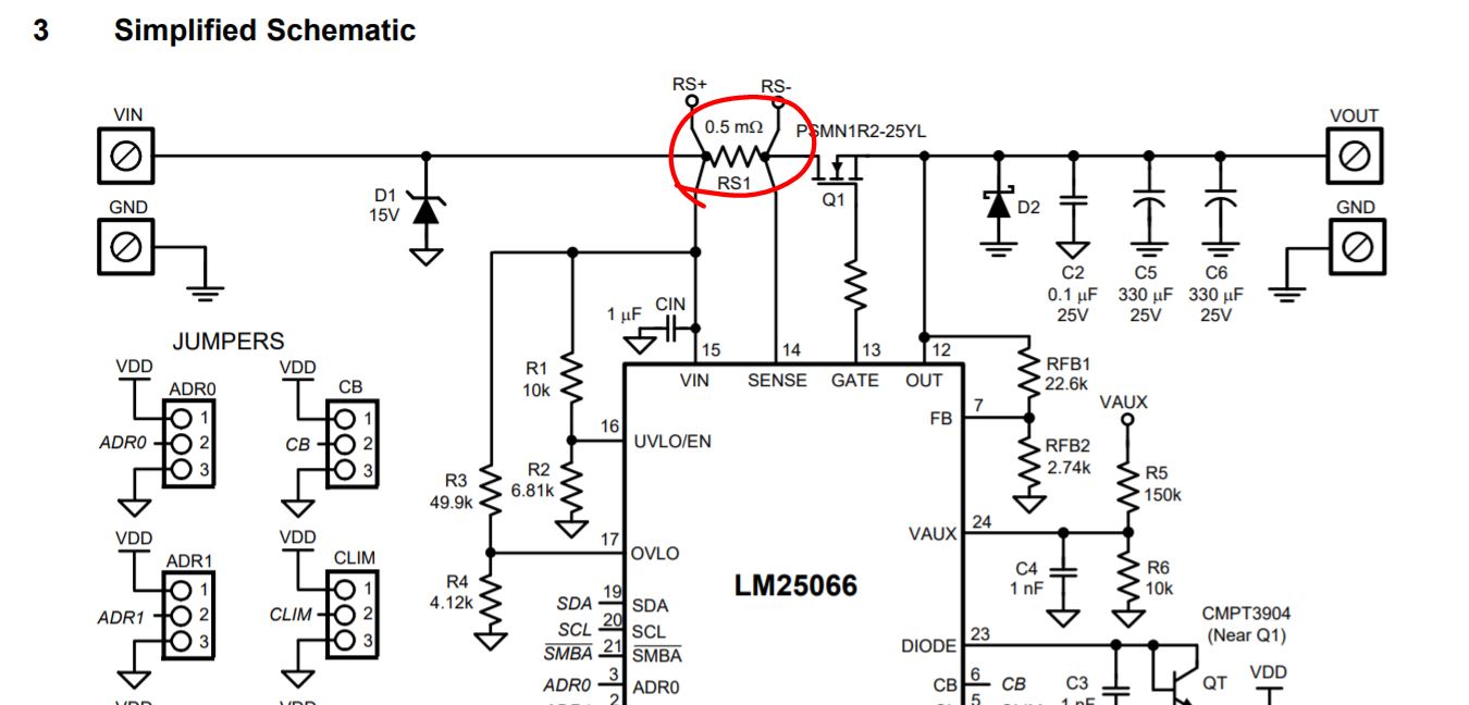
My customer has changed RS1 on EVM to 10m Ohm, and he found that the current limit wasn't triggered when the voltage across RS reached 25mV(2.5A load current), but based on my understanding, fault timer should be triggered.

Is there anything that I might misunderstand here?

  • Hi Charles,

    Yes, with RS1 changed to 10 mohms, the current limit has to be at 2.5 A.

    • Can you please check if RS2 is populated on the EVM ?
    • IS the current limit behavior working as expected for different RS1 values, like 5 mohms, 1 mohms ?
    • Can you please share the following waveforms
      • Vin, Gate, Iin, Timer
      • Vin, Gate, Iin, Vout

  • Hi Praveen,

    Thanks for your reply.

    I am not sure what "RS2" refers to, do you mean an additional sense resistor?

    Regards,

    Charles

  • Hi Charles,

    There are two sense resistors on the EVM. Please refer to EVM schematics in Figure 23, Page no 18 of EVM User Guide

  • Hi Praveen,

    RS2 is NC on EVM, as for the waveforms, please refer to the attachment, thanks.

    7026.waveform.docx

  • Hi Charles,

    From the waveforms you shared it looks like you are applying load during startup. Can you confirm this ?

    During startup, the device will be in either current limit / Power Limit / dvdt based startup. If there is load during startup there will be more stress on the FET and there is a possibility of damage. So, I would encourage you to use the design calculator available in the product folder to understand how much load is acceptable during startup for a given system conditions like total output capacitance, FETs used, Max Vin, Timer Duration, Max Amb . Temp, etc..

    I would recommend you to startup with no load and then apply load in steady state and test the current limit functionality of the Hotswap, LM25066. 

    For more understanding, you can refer to Robust Hotswap Design App note. 

  • Hi Praveen,

    I have attached another waveform during steady state, the current limit function still doesn't work, does it indicate that there might be some components damaged?7433.waveform.docx

  • Hi Charles,

    1. Can you please explain how your test setup is?
      1. If possible please share images.
      2. The reason for asking this is there is voltage drop at input with increase in load current which suggests high resistance in the path.
      3. What is the load being used here ? Is it an e-Load ?
        1. If it is a e-Load DO NOT test it is CC mode. Use CR mode fr current limit testing
    2. Can you keep increasing the current with CR load and check at what point is timer starting to ramp up and device turning off after timer expires. 
    3. Is the current limit behavior working as expected for different RS1 values, like 5 mohms, 1 mohms ?
      1. Please share waveforms with different current sense resistors
    4. Have you tried replacing the IC and repeat the same experiment ?