This thread has been locked.

If you have a related question, please click the "Ask a related question" button in the top right corner. The newly created question will be automatically linked to this question.

TPS62150A-Q1: Short-circuit protection Inquiry

Part Number: TPS62150A-Q1

Hi,

Good day. I hope you are well.

Our customer wants to use the TPS62150A-Q1 on their design and they want to protect the 5V VDD output for short circuit to Battery and GND. So, they have added a general purpose diode between Inductor and feedback path that will help for protection. Is this the right way to do this? Also, they want to know the implication of the D2 in the circuit attached.
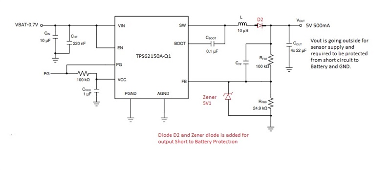


We would appreciate your suggestion on this. Thank you/.


Regards,

Cedrick

  • Cedrick,

    Are you trying to protect our device or the downstream components connected to the 5V output?

    Thank you,

    -Matt

  • Hi Matt,

    Thank you for your response.

    The customer is trying to protect our device (TPS62150A-Q1).


    Regards,

    Cedrick

  • Cedrick,

    I do not recommend placing a diode in series with the inductor.

    Given the device has built in short-circuit and thermal protection, you only need to really protect against the potential short between Vout and Vin, which can be protected with a zener between Vout and GND tot prevent VOS from exceeding the 7V Abs max rating.

    Sincerely,

    -Matt

  • Hi Matt,

    Thank you for your answer.

    One more thing, I've just got an update from our customer, they also want to protect the Vout pin from possible short to Vbat (VIN pin). Do you have any recommendation on how they can achieve this?


    Regards,

    Cedrick

  • Cedrick,

    I'm not sure how this request is any different than the previous one.

    As the VOS pin must be directly connected to Vout, the above recommendation was specifically intended to protect the VOS pin as this pin has a 7V Abs max rating which could be exceeded if Vout/VOS was inadvertently shorted to VIN/Vbatt.

    The only additonal detail that i can add, is that I would expect the zener diode to be placed in close proximity to the primary output capacitor (closest to the IC if multiple caps used) which should also be where the VOS pin is tied (Kelvin connection).

    Sincerely,

    -Matt