This thread has been locked.

If you have a related question, please click the "Ask a related question" button in the top right corner. The newly created question will be automatically linked to this question.

Output Failure Rate Analysis for TLV431-Q1 on High Temperature

Other Parts Discussed in Thread: TLV431B-Q1, TLV431B, TLV431
Hi Expert,
I am a FAE from MM of CHINA. TL431B-Q1 was used in this customer. There is a failure case on customer side. Could you help on that?
It's better if you can send email back to me. Thanks.
 
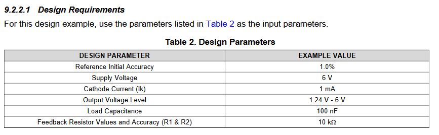
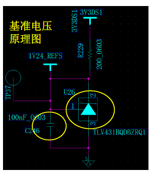
Customer is following this guide, see the schematic:
Vin =3.3V, Vout =1.24V; CL= 100nF,
Output Fail rate: 2% (19pcs in 1000pcs, when ambient temperature = 90C)
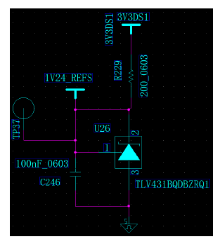
When customer test this device on end customer side, they find that, when the ambient temperature on TL431B-Q1 increase to 90, the output is unstable, here is the output I got from customer side:

Output of TLV431B-Q1 when the ambient temperature increase to 90

Here is the action and test customer did:
Change the output capacitor to 1nF, the TLV431B-Q1 output will stable when the ambient temperature rise to 90C.
Question1: This Capacitor change t0 1nF, Is there any risk for this change?

Otherwise, for the datasheet version, customer has other question,
2008 datasheet(Left figure) and 2017 datasheet(Right figure)
The left figure is about the stability of tlv431b in the 2008 datasheet, which was removed in the 2017 datasheet and replaced by the right figure. From the left figure, CL = 100nF is completely stable, but there is only a few degrees of phase margin in the right figure.
 
Question 2: there are important changes in the relationship between Cl and stability in the two versions of the specification. What are the reasons?


Best Regards

Songzhen Guo

  • Hi Songzhen,

    The B grade of the TLV431 should use the graph from the latest datasheet such as figure 19.

    Q1. 100nF is the most unstable region for this variant and I would highly recommend to switch to a larger value. The stability of the TLV431 on the graph is shown with 0 degree phase margin and at 25C. Temperature will make the device much more unstable which is what you are experiencing.

    Q2. The graph was updated from the old datasheet to the new one to better reflect the device performance. The old graph did not show how unstable the device can be at 0.1uF because the TLV431 stability has variation from device to device. The new graph is more conservative but it shows to stay away from 100nF.

  • Hi Marcoo,

    Thank you so much for your feedback.

    For Q1, in order to improve the phase margin, we can switch to a larger CL, but it will slow the feedback response time; When we go back to the Figure 19, it also can improve the phase margin when switch to a lower capacitor. Could you comment on that? Thanks.

    Otherwise, there is a example in datasheet, the scenario is similar to customer's requirement: Vin =3.3V, Vout =1.24V; It recommend a design parameter, the CL is 100nF. Could you comment on that? Because followed this design, so they use 100nF in their board. Thanks.


    Best Regards

    Songzhen Guo

  • Hi Songzhen,

    That is a good catch. I am unsure on who made that table in that example. I will request to get it changed. If you cannot use a larger capacitor then use a smaller one.

    Based on the original post's schematic, the TLV431B is biased around 10mA so you can use lower values around 1-10nF. Can you test these values and see if you still see the issue?

  • Hi Marcoo,

    Thanks for your feedback.

    I confirmed this with customer. When CL change to 1nF. The issue is disappeared. Thanks.


    Best Regards

    Songzhen Guo