This thread has been locked.

If you have a related question, please click the "Ask a related question" button in the top right corner. The newly created question will be automatically linked to this question.

BQ76952EVM: Board Queries : OCC threshhold , Cell balancing settings , upgrade for a larger BMS system ( 150A + )

Part Number: BQ76952EVM
Other Parts Discussed in Thread: BQ76952, BQSTUDIO, BQ40Z50, BQ4050, , EV2400, BQ76942, BQ79616-Q1

Hi team TI

I am using the BQ76952 evboard for 4s LiPo4 cells and controlling the cycling between loads and a power supply using a single board computer ( host processor using i2C ). I have faced the following issues :

1. Even tho I have set COV and CUV threshold to 4V and 2.5V respectively, the charging doesn't occur above 3.4-3.5V and OCC ( over current during charging) register goes high even tho I have set 3A on my power supply which is 0.5C of the battery pack. Can I know how can I allow the charging to take place at higher current values like 4A without having the OCC error to show up. here I also want to know the OCC register settings which show 4mV as default for the current sense resistor, what should be its value in order for me to allow higher currents to pass through the board ( i.e. greater than 3A and less than 6A). 

2. this board as said in the manual can have a max balancing current of 65mA so acc. to this how long will it take for the balancing to fully complete as the cell balancing takes too long and I am not able to have a balanced voltage between these 4 cells. during the charging cycle, even tho I have set balancing to occur after 3V. should I lower this value more but then balancing will take quite a while. (right now I have set my supply to be 14.4V at 3A)  but the pack never charges to this since one of the cells reaches the limit while other cells are still behind it. for eg cell 1 reaches 3.5 while cell 2 and cell3 are sitting at 3.4V and 3.3V. Can you guide me with what mistake I might be doing in the cell balancing settings? 

3. This board uses a series combination of FETs for charging and discharging, is it possible to have both FET's closed ?( both charging and discharging to happen simultaneously). as I want to make my own 150A LiP04 (16s- 48V) system using your battery monitor and balancer ICs from this model but then with the higher current path, what would be your recommendation on whether I should be using two contactors or series of anti-parallel Mosfets to carry higher currents out of the board. Of course, I will be developing my own schematics for the PCB design but I want to be first sure about the changes I should consider while upgrading your product for higher current capability. using MOSFETs does give losses (Rdson) but are they significant compared to having contactors ? 


Sorry for the long query but I am really confused with these doubts, hope to get the response soon :) 

Kind Regards
Bilal

  • Hi Bilal,

    For information on configuring the BQ76952, see the technical reference manual. 

    1. See 13.6.4.1 Protections: OCC: Threshold for the threshold setting and 13.6.4.2 for the OCC Delay.  Default threshold is "2"  of "2 mV" units or 4 mV with a delay of "4" "3.3 ms" units or 13.2 mV.  There will be a tolerance on the settings, but check your supply for variation, if the supply varies current may trigger the fault.  Increasing the delay may be reasonable, or increase the threshold.  Check OV and UV as well, but you indicate seeing OCC, so current variation would seem to be the issue.

    2. The balancing system in a monitor is mostly to maintain balance.  LiFePO4 cells will be difficult due to the flat voltage curve.  I may misunderstand your situation, but if you have 150Ah cells which have a 10% capacity difference this will be 15 Ah. With 64 mA balancing this can take 15Ah/.064 A = 234 H to balance out.  In LiFePO4 cells the voltage difference mid-range may be very flat and a difference may not show up until near full charge.  Near full charge part of the voltage apparent on the cells may be from IR drop from charge current, so you will need to check carefully to determine which cells to balance.  Check with your cell manufacturer for recommendations on balancing.  You may find that balancing during idle is best for your system.    For settings for the BQ76952 see the application report https://www.ti.com/lit/pdf/sluaa81  

    3. It is common to have both charge and discharge FETs on at the same time so that the current can flow in or out of the battery as needed.  By default the BQ76952 has SLEEP mode enabled so that it turns off the CHG FET and reduces operation when it measures current below a threshold to reduce power and extend battery life.  When current is measured above the threshold it returns to NORMAL mode turning on the charge FET and staying awake to monitor the current and battery status. You can configure sleep mode settings if desired.  The BQ76952 is designed to drive FETs in small to medium or even large batteries where the monitor checks current and can turn off the FETs to interrupt current in as little as 10's of us.  FETs are typically used for fast response.  (Battery size is a relative concept, there are typically smaller and larger systems than the one under consideration.) There are other system designs such as automotive where the monitor is used to check voltage and temperature only with current monitoring separately and current control is commonly done with contactors as you mention.  These often have alternate power sources to provide control in the event of short circuit events. Contactors may switch more slowly than FETs.  The BQ76952 can drive multiple FETs as noted in the application report https://www.ti.com/lit/pdf/sluaa09  but certainly there is a practical limit or your system may have a situation or requirement for a contactor.  You will need to determine the best solution for your design.  You have many design options including interfacing the BQ76952 outputs to a contactor drive or using only the voltage and temperature monitoring of the BQ76952 and using a separate current measurement system with your host determining when to control the contactor.   

  • first of all thanks for the quick reply, I still haven't got the answer I am looking for :(. I have read the tech ref manual and other by studio manuals already but I still have this issue present, the cells I am using are 6Ah 4s LiFePo4 (3.2V nominal) ones and they are from a Chinese manufacturer (I don't remember exactly which one ) without any datasheet.

    1-  I have already set COV andCUV to 3.7 (as opposed to 3.65V) and 2.5V respectively. but the supply current is 3A (0.5C) and it doesn't go higher than that, I have verified that. The issue I want to ask is that what does increasing the threshold means here with regards to 2mV units, since I don't know the value of the sense resistor, this threshold corresponds to the voltage measured right or am I wrong. how I think is that If I know the resistance then by ohms law I can divide this threshold voltage over it to get the current allowed for charging Please correct if I am wrong. 

    2- My end goal would be to hook up some higher energy cells such as 280Ah LiFePo4 cells and use some external fets for at least having higher balancing current using your battery monitoring and protection IC but before that, I am testing it on a smaller scale using this 6Ah one. Please I want to have a clarification on this point that is passive balancing correctly going to work for my current 6AH 4s cells considering a balanced current of max 65mA? you are def right about the flat voltage curve for their chemistry but I have been cycling them quite alot now but always I am left with 1 or 2 cells being too higher than the rest. for eg cell 1 would be at 3.7V while cell 2 and 3 would be 3.4 and 3,3V. I only see similar voltages ( 3.3-3.4 V) for a small period of time and then towards the end of charging 1-2 cells quickly shoot up and passive balancing does nothing there. because of that I never reach the full voltage (14.6V considering 3.65V/cell). As the COV protection triggers this doesn't allow chg until cell 1 comes down but the moment it comes down a bit , chg starts and it again goes to 3.7V and above and this process goes forever until I initiate the discharging process from my host processor. Please I need help in this area as this is the primary function of a BMS, to even out the imbalances and I have still not achieved this result yet. if not LiFePo4 then for what other chemistries is this BQ76952 batt monitor and balancer designed for? 

    Right now I am running autonomous balancing so to verify the IC's functionality and I am yet to achieve a good result with having 4 cells sitting at 3.65V each. In the Cell balancing settings, I have set the min and max voltage ranges to 2.8V and 3V corresponding to when the balancing should begin. would you recommend changing it at a higher value like 3.4V as you said earlier the diff arises towards the end of charging? I want to know your recommendation on this. considering 65mA balancing current for a 6Ah cell, 6Ah/0.065A = 92h to balance out right?  does that mean then this lithium chemistry cell shouldn't be used with this board or use at least external balancing fets for at least 1A balance current to have it done in 6h? if yes then how about 280Ah cells? what would your balance current recommendation at least to have it on the external balancing circuitry? 

    3-  As you mentioned already that there are design options interfacing the BQ76952 outputs to a contactor drive , I want to know how does this monitor supports the contactor controls since as acc to the ref manual one of the external thermistor pins can be used for driving a contactor or am I wrong? I have read the manual of having external MOSFETs in parallel but my application would actually exceed the voltage and current that they can handle also comes the losses compared to contactors. what I haven't seen is any BQ76952 manual explaining the use of contactors with it.Can you elaborate that how is this possible to achieve if one doesn't want to imply the parallel fets conf for the higher current control? 

    Another point that you suggested was that I can do voltage and temperature monitoring of the BQ76952 and use a separate current measurement system with your host determining when to control the contactor. but in that case, I want to also utilize the protection functionalities offered by this battery monitor and protector so in that scenario, how would I do realize such a case? i,e, to be able to control my contactors based on the current protections read by this IC. what are the pros and cons for this suggestion that you proposed me as the only thing which makes me think not using MOSFETs
    is that rds on and switching losses that they offer.   

    4- Last but not least, can this monitor display the SOC in the studio? only thing I have seen is the accumulated charge in Ah and time for that in s.  Acc to my understanding SOC = cap remaning / total capacity , considering my 4s 6Ah cells case, would this mean to divide the acc charge (Ah) register as shown in bq studio by 6 (because 6Ah cells ) and then I would be able to get SOC ratio. Is this correct thinking ? please throw light on this topic also

    Thanks a lot for your time and consideration

    Yours sincerely 
    Bilal 


  • Hi Bilal,

    1. Yes, it is ohms law.  The EVM has a 1 mOhm resistor, so 1A is nominally 1 mV, but there is solder resistance also.

    2. Yes, the part is designed for LiFePO4 and other li-ion chemistries, but it can only work within its capabilities it can't solve every need.  The part can balance autonomously in charge or relax mode, but if the cells fail to maintain a recognizable voltage it will stop as described in section 10.  You could continue to balance with the part controlled by a host which knows the capacity of the cell if you have that.  The host could avoid the cycling you describe.

    Balancing in the BQ76952 will be most effective in maintaining balance of matched cells when recognizable to the algorithm.  Balancing cells assembled with mismatched state of charge will be difficult for it to balance since the BQ76952 has no knowledge of state of charge.  It is an external gauge or host which can know or estimate a state of charge.

    3.  No the BQ76952 does not support contactor drive.  If you are uncomfortable designing an interface between the BQ76952 and a contactor see a design consultant or select a part with a suitable interface.

    4. The BQ76952 does not know or provide SOC (edited 1/20).  It can accumulate passed charge, but has no capability to know or calculate a SOC. This must be handled  by a host with a gauging function. BQStudio is an interface tool, it does not provide a gauging functions.  It does support gauges, but none are designed to work with the BQ76952. 

  • 1- According to that as seen in the bq studio settings the native units are in 2mV so setting an OCC threshold of 6mV will correspond to 3A ?

    2-  Can you elaborate more on this " it can only work within its capabilities it can't solve every need" . the cell balancing happening here is my biggest concern because BQ76952 supports 16 cells in series and  I am just using 4 cells of LiFeP04 chem 6Ah in series and they arent being balanced properly during charging stage.Is setting autonomous balancing min Voltage in the Cell balancing settings to 3.4V a good idea? since its closer to 3.65V ( for full charge). later on I want to hook up some really high amperage LiFeP04 cells 100Ah or more. I am just wondering whether this BQ76952 the right solution for them or not. Yes I know I will use external FETs for balancing them but the cells which I have are smaller and I get unbalanced voltages for each of them . 

    How should I know if the balancing is recognizable to the algorithm ? I am using new 4s cells for testing purpose and the passive balancing doesnt work correctly. You said that the BQ76952 has " no knowledge of state of charge " but in the last point you contradicted your own claim saying that " The BQ76952 does know or provide SOC " . Can you please clarify this point . 
    So if there happens to be a cell which has dropped its SOC compared to the other ones then your saying that this battery monitor will never be able to balance all of them evenly? the only solution left will be to discard that one cell ? 

    if the idle mode is the one you suggested me above then what should be my settings to make sure balancing is happening correct , which registers should I consider changing in this case. 

    3- Yes I figured that but in the tech ref manual sec 6.7 for "DDSG and DCHG Pin Operation" , there it is written that control of external protection circuitry is possible using the DDSG and DCHG pins where digital a general-purpose digital output can be used based on fault-related signal. Can the contactor design be used for such a logic level circuitry using these digital charge and discharge pins? 

    4- If the BQ76952 does know or provide SOC which I have seen in the BQ studio as acc charge in Ah and also the time passed then how can't it not use that for cell balancing algorithm. If it doesn't provide guaging functions except for the current then do you have a separate IC from the range of the products that does this job which I can integrate with my host processor ?  If it support guages then can you suggest or recommend me any that can be compatible to use along with the BQ76952. just a query that if I divide this passed acc charge by 6Ah  ( as for my current cells Ah capacity) , wouldn't that be its present state of charge or I am wrong in this calculation approach. 

    5- this query is with regards to using the i2c interface with my host processor displaying the measured voltages and current etc values , normally I have turned off the auto refresh on the BQ studio so not to have clash with two microprocessers (one its own and the other which I am using ) but at times I receive some irrelevant data on my host . Is there clock streching happening or should I disconnect the usb cable from my laptop at all times when doing the i2c comm . does this have any effect on this . do I need to add a pull up resistor on the i2c pin in this case ? 

    as always thank you for your valuable suggestions.

    Yours sincerely
    Bilal 


  • Hi Bilal,

    1. If native units are 2 mV and the value stored is 0x01, the parameter is 2 mV.  If the value stored is 0x06 the parameter is 12 mV.  To make this more confusing BQStudio will do the conversion for us sometimes, the parameter will display 12 mV for example, but if you read the address it will show 0x06.  In your example a setting of 0x03 of the 2 mV units would be a value of 6 mV which when divided by 1 mOhm would be 6 A.  If native units are 2 mV you can never get a 3 mV setting (3A with 1 mOhm).

    2. " it can only work within its capabilities it can't solve every need".  BQ76952 is intended to drive FETs.  It can't drive contactors.  You might be able to design something to interface to it, but it won't do it alone.

    BQ76952 is not a gauge.  You can measure voltages and currents and passed charge with BQ76952 using a host MCU and do some gauging in the MCU.

    The BQ76952 does not know SOC.  Thank you for pointing out the error in the post yesterday.  I don't know where the "not" went, I have edited it.  So BQ76952 only has voltage and current available for balancing control with its algorithm.   If all cells are at 3.2V but some are lower SOC and when charge current is applied the higher SOC cells jump to a protection level of 3.65V and the part cuts off charge, the lower cells will not charge if the voltages fall back to within the limit of Settings:Cell Balancing Config:Cell Balance Min Delta (Relax).  

    To balance during relaxation (when idle), set Settings:Cell Balancing Config:Balancing Configuration[CB_RLX].  See the description in section 10 of the technical reference manual and with the command descriptions in section 13.3.11.

    If your host knows that 1 cell for example goes to UV first on discharge, and the others go to OV first on charge, it could know to balance the others longer.  If the host can estimate that the cell has x mAh lower SOC, it can balance the higher cells for x mAh, or some fraction of that to avoid overshoot to try to balance the cells over several cycles.  If you host observes that the same cell reaches OV first and UV first, that cell must have a lower capacity or higher resistance, the balancing can't fix that, the lower capacity would have to be accepted or the cell would need to be replaced.

    3. Electronic design can be very versatile.  I would expect you could design an interface from DDSG and DCHG to a contactor driver. You might want your host to input to the logic as well, or instead.

    4. The missing "not" in the post created confusion. It has been corrected.  Thank you for your patience. BQ4050 and BQ40z50 are 2 gauges which support 4 cells.  Capacity is limited so scaling will need to be used, see the latest versions of those products if interested.

    5. I2C needs a pull up.  Pull ups to REG1 are available for I2C on the BQ76952EVM on J15 and J18. BQ76952 can do clock stretching although the term shows up only once in the TRM.   BQStudio has both the dashboard which will update every 4 seconds by default and the register scan feature.  These are controlled separately.  Be sure both are stopped. 

  • 2- So the balancing works best when the cells are in a very similar voltage level since the beginning right ? and if there are one or two cells having mismatched SOC then the balancing won't take place and it would stop as you mentioned earlier if " if the cells fail to maintain a recognizable voltage" but I couldn't find this point in sec 10 of tech ref manual that it will stop balancing it. usually, is it better to do an autonomous balance or Host controlled one?  In my case seems like host-controlled is the way to go since autonomous loses its track completely as it doesn't know the SOC. it does balancing based on voltage algorithm only I believe. so in a  case where cell 1 is going 3.65V + quickly than others towards the end of charge will other cells were at 3.4V, this would result in COV case and will stop the charging process so here the balancing won't do much of its work since now the voltage differences between cells are 200mV  right? 

    as you mentioned above lower cells wont charge unitl voltage falls back to within limit but at the same time as the voltage for the highest cell falls back a little from 3.65V to 3.59V for eg than the charging begins again and the whole process repeats but cells never get to be in a similar voltage level. any solution for this issue?

    4- thanks for highlighting the products but I would like to design for hihger capacities so would you mind giving a suggestion for any SOC calculation method to go for using my own Host. I dont have knowledge in the SOC calculation so it would be nice If I can get some guidelines to follow :) 

    5- So just putting those shunts on the SDA and SCL lines as also used for the unused cells would suffice right as they are connected to the REG1. ( btw is this stands for register 1 used as a voltage source? ) . what impact does it have if the dashboard and the reg scans are not turned off for eg? is there like a master-host clash or something like that ?    

    Yours sincerely
    Bilal 

  • 2- So the balancing works best when the cells are in a very similar voltage level since the beginning right ? and if there are one or two cells having mismatched SOC then the balancing won't take place and it would stop as you mentioned earlier if " if the cells fail to maintain a recognizable voltage" but I couldn't find this point in sec 10 of tech ref manual that it will stop balancing it. usually, is it better to do an autonomous balance or Host controlled one?  In my case seems like host-controlled is the way to go since autonomous loses its track completely as it doesn't know the SOC. it does balancing based on voltage algorithm only I believe. so in a  case where cell 1 is going 3.65V + quickly than others towards the end of charge will other cells were at 3.4V, this would result in COV case and will stop the charging process so here the balancing won't do much of its work since now the voltage differences between cells are 200mV  right? 

    as you mentioned above lower cells won't charge until voltage falls back to within limit but at the same time as the voltage for the highest cell falls back a little from 3.65V to 3.59V for eg than the charging begins again and the whole process repeats but cells never get to be in a similar voltage level. any solution for this issue?

    4- thanks for highlighting the products but I would like to design for higher capacities so would you mind giving a suggestion for any SOC calculation method to go for using my own Host. I dont have knowledge in the SOC calculation so it would be nice If I can get some guidelines to follow :) Is it possible to use any algorithm using the BQ76952 acc passed charge to register and acc passed charge time ? 
     
    5- So just putting those shunts on the SDA and SCL lines as also used for the unused cells would suffice right as they are connected to the REG1. ( btw is this stands for register 1 used as a voltage source? ) . what impact does it have if the dashboard and the reg scans are not turned off for eg? is there like a master-host clash or something like that ?    

    Yours sincerely
    Bilal 

  • Hi Bilal,

    2. The balancing will work the same with similar voltage (SOC) or not.  If the voltage difference is the same the part may not be able to recognize it depending on the thresholds and accuracy of the measurement. If measurements are recognized and above the thresholds cells which are matched will balance sooner. 

    Autonomous balancing is simple to develop, it should be just setting parameters for the autonomous algorithm.  From your experience it seems LiFePO4 cells may be difficult to set suitable parameters.  Host balancing takes more work in that an algorithm must be coded.

    If the cell voltage drops immediately when current stops it seems it may be a cell resistance phenomena.  You might check with your supplier to see if they have recommendations of voltages excursions which are normal.  If you have old mismatched cells they may not represent what you will see in a real prodduct production situation.  At end of life the behavior may not be as good.

    4. We don't have a "how to design gauging" document. You might find something in educational literature.  The accumulated charge register should be helpful in measuring charge over time and should get you the capacity between OV and UV.  The challenge is often how to predict the future condition of each cell.  You may need to know the capacity of each cell at the beginning of life and watch it change over time to estimate capacity. 

    5. Installing the shunts for the pull ups will connect to the regulator.  The regulator also has to be enabled.  REG1 stands for regulator 1, it is also the pin name.  BQStudio processes will not collide with each other (register scan and dashboard update), but either could collide with a MCU connected to the bus.

  • 2- " The balancing will work the same with similar voltage (SOC) or not"  ? does that mean even if SOC imbalances are quite significant the balancing will still occur but for my case, the cells never reached a considerable voltage level . One very imp question arises here as I remember you previously mentioned that balancing is done using a Voltage algorithm but normally for a BMS system balancing algorithms are designed based on some sort of SOC  estimations. How is it happening here in the BQ76952 by just using voltage readings as a balancing estimator?

    You already said previously that sec 10 " cell balancing " describes the automatic shutdown of balancing if the voltages have a significant diff but I couldnt find something similar written there. Can you please clairify this point . 

    4- So as you stated up , if I plot the acc charge register verses the acc charge time , I would be able to get a capacity graph between the OV and UV limits ? for my 6Ah case would it make sense if I divide this acc charge in Ah over the 6Ah cells capacity in turn to display capacity in percentage? Please correct me if I am thinking wrong.

    5- I have used the same small shunt is provided along with the board for shunting the SDA and SCL lines , how can the regulator 1 ( Reg1) can be enabled and under what section does this info lie in ? isnt it enabled by default and if not then what voltage would it be set to ? 1.8 , 3.3 or 5V ? 

    Yours sincerely 
    Bilal

  • Hi Bilal,

    2. Right, if the SOC is almost the same with little voltage difference between cells, and that voltage is across the threshold the part will balance just as if the SOC were large with a large voltage difference between the cells and the voltage were across the threshold.  The challenge is clearly recognizing the voltage.  The BQ76952 has a VCELL(ACC) of +/- 5 mV at 25C (see the data sheet), so if the cells are 10 mV apart indicating a SOC difference, but the tolerance on that particular part at that voltage has one cell high and one cell low, both could show the same voltage and would not be across any threshold.  If while charge current was present the cell voltages were 200 mV apart the IC could recognize them as being separated by the Settings:Cell Balancing Config:Cell Balance Min Delta (Charge), but then when charge current stopped if they drop back to that 10mV difference reported by the cells as the same value there would be no difference to be above the Settings:Cell Balancing Config:Cell Balance Min Delta (Relax).  So balancing would operate only very briefly.  To be effective with this type behavior you need an algorithm which can remember behaviors and past conditions and operate for some time to balance the cells.  A host balancing algorithm could do that.

     See the descriptions in 10.1.  Many parameters are mentioned by name, details on the parameters are in 13.3.11, you may have to switch between the sections.

    4. The cells should have a voltage vs charge curve which shows a capacity.  For 6 Ah cells there should be at least 6 Ah, usually there is some margin.  With the cells together in a battery you should have 6 Ah capacity or more between OV and UV, passed charge should show that.  If your passed charge is showing less then the pack is likely imbalanced or a cell has lost capacity.  For example if you only get 5 Ah from the pack and cell 1 goes to UV first and cell 2 goes to UV first, you can see that cell 1 is at a higher SOC and cell 2 is at a lower SOC.  Cell 1 needs to be balanced down some.  Cells 3 and 4 may need balanced down some also.   As another example if you only get 5 Ah capacity between OV and UV, and cell 1 goes to OV first and cell 1 goes to UV first, cell 1 has lost capacity  Balancing won't help.

    If your gauging algorithm knows the SOC from voltage and you can measure the voltage difference, you can estimate as you indicate.  The data sheet from the cell manufacturer may give information from the curve for you to predict.  It is hard with cells with a flat voltage curve.  In the middle of the range you can't tell from voltage if there is a 1% SOC mismatch or a 10% SOC mismatch.

    5. The BQ76952 has the REG1 off by default.  As delivered the EVM board has pull ups for I2C provided by the EV2400 (MSP430) circuit on the board, 3.3V derived from the USB 5V.  If you disable activity from BQStudio but leave the USB cable connected the pull up will still be present.  To use the pull up to REG1 on the shunt positions noted, configure REG1 to the desired voltage. See 6.3.1 Pre-Regulator Control and 6.3.2 REG1 and REG2 LDO Controls in the technical reference manual.  You really don't want the pull-ups fighting, particularly if you select a voltage which might be damaging to the other system, so think through how you will want to program, then make connections, in this case when to install the shunts if you choose to use the REG1 pull up, and when to disconnect the EV2400 circuit.  If you program the regulator settings in OTP the BQ76952 returns to those settings at power up.  See the EVM user guide for information and schematics of the circuit, https://www.ti.com/lit/pdf/sluuc33 .

    For setting the voltage for REG1 it is normally set to something your MCU can understand, one concept is that REG1 may power the MCU. 

    You don't have to use REG1 to provide the pull ups for I2C.  Like the EV2400 circuit provides the pull ups for the board in default configuration, your MCU board could provide the I2C pullups.    

  • HI TI Expert,

    2- Earlier in our discussion you said that BQ76952 wont do balancing if the SOC and voltage diff are significant and above the threshold limits but now you say that it will be work for both cases ( small diff or large diff). I am so sorry but I am not able to fully understand this part which you explained up with the tolerance and cell balacing conf . Can you please rephrase in a better way so that I can understand . I apologize for this but I couldn't get to your point. I do know that VCell accuracy on the BQ76952 s upto +-5mV but the part after it I didnt get it at all.

    4- I am confused with the part where you say cell 1 and cell 2 will both hit UV first or did you wanted to say cell 1 reaches first than others ?  "The cells should have a voltage vs charge curve which shows a capacity" , do you mean here that if plot the cell voltages versus the acc passed charge register , I would be able to see capacity. but the register of 'Accumulated passed charge" is in units of Ah , here arises a confusion that what should be chosen on the scale to plot. can you please guide here. 

    5- So what I understood here is that REG1 shouldn't be used for pullups . when the usb cable is connected 3,3V is taken from the 5V EV2400 circuit. but what if I disconnect the USB cable and let the EVM run normally then I need to configure REG1 acc to the TRM right? Can you please tell me the use of Pre-regulator and REG 2 LDO controls as you mentioned up . what role will they play in such a scenario . when I measured the voltage from the i2c data and clock lines I was measuring 3.3V so I can then assume that they were powered by EV2400 which basically regulated 5V to 3.3V ? I am a bit confused with this now as before normally I used to just connect to EV2400 to see the registers and dashboard and then used to remover the cable and use my host to monitor battery cycling. so in such a scenario what would be your reccomendation . Should I change setting for REG1 then or also LDO REG2 too. my aim is to have pull ups present for the i2c always. whats the use of Pre-regulator in this case ? also even tho I didnt changed the default settings I was reading 3.3V at REG1 terminals . hows that possible when you said the BQ76952 has if OFF by default.  .  

    Yours sincerely
    Bilal 

  • Hi Bilal,

    2. I made a typo early on.  You must forget it.

    See cell balancing for BQ76952 in this video starting 5:55.  https://training.ti.com/bq76942-bq76952-battery-monitors-fet-configurations-and-cell-balancing 

    You need to look at your voltage curves for your cell.  See your manufacturer.  It will have some representation of passed charge at a certain rate.

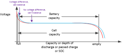
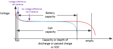
    When the cells match but the SOC is different, there will be a voltage difference you can see.  If it lasts past the charge current stop, you can set thresholds to balance.  If it falls so much that there is no voltage difference, BQ76952 can't balance by itself.  If the host knows what happened, it can control balance.

    If one cell loses capacity, it goes to OV and to UV first.  Balancing may align the cells at the top, but can't fix the capacity difference.

    4. Capacity curves will be at some rate, or sometimes multiple rates generally with more capacity at lower rates.  Current is A, time in hours, current x time is Ah.  Vendor curves are usually in C rate, its rated capacity in 1 hour, see their definition and explanation.  It can be confusing.  

    5. If/when you disconnect the EV2400 circuit which provides the pull ups for I2C, you will need a pull up either from your host or the BQ76952 circuit.  The choice on the BQ76952 board is REG1.  the pre-reg on the part works to bring the battery voltage to 5.5V nominal.  It must be enabled in configuration.  The REG1 regulates the REGIN from the pre-regulator to the desired voltage, usually what your MCU uses. REG1 would need to be selected and enabled in configuration.  It is easiest if you provide pull ups from your MCU.  

    REG1 does not have a voltage normally on the BQ76952EVM.  Some IC versions may be available with the regulator enabled.

  • HI Ti Expert, 

    First of all thanks for the graphical explanation , however the point where you said "   If it lasts past the charge current stop, you can set thresholds to balance.  If it falls so much that there is no voltage difference, BQ76952 can't balance by itself." is still unclear to me . What I understood is that the SOC diff shows towards the start and end of charge-discharge processs becasue of the LFP chemistry voltages remain quite flat.. But what I still want to inquire is that whether cell balancing is working here based on voltage algorithm only without any SOC estimation or calculation based algorithm? because as far as what I have read is that Cell balancing works based on SOC algorithm . If I am wrong then please correct me and also enlighten how can cell balacning work just on a Voltage based algorithm . Yes I do know that cell balancing can only correct SOC diff and not cap or internal resitance etc . but I remember that you said ealier in this thread that balancing on BQ76952 only works based on Voltage based algorithm. Is it feasible to have just this info for balancing act specially for a LFP chem where thr voltages remain the same even when the cap decreases. Also in the first graph , waht did you meant by when the cells match ? do you mean that cell 1 (Red) and cell2 (possibly blue) are having same voltage but cell 1 (red) has higher capacity than cell 2 , thats why we have SOC diff ? sorry again but I really need to understand the exact methodolgy which the BQ76952 is using for cell balancing considering the LFP chem so that then I can decide what my host needs to do as I saw in the video that it can only balance non-adjacent cells . and having 16 cells in series there  , what will happen if  I choose higher no of cells to be balanced simultaneously in the cell balancing settings using the bqstudio . can I choose for eg 8 or 10 ? what are the consequences of it ? 

    Yours sincerely 
    Bilal
     

  • Hi Bilal,

    If when charging one cell is 3.4V and one cell is 3.6V, the BQ76952 can see the difference and if the threshold is set properly it can balance the 3.6V cell.  If the charge current stops and the cells read 3.333 and 3.334 V even if it has been set to balance during idle the BQ76952 won't balance because it won't be above the idle balance threshold.

    BQ76952 is always voltage based balancing.  For SOC based balancing the control must be done by the host which knows SOC.

    "... in the first graph ... when the cells match ?"

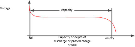
    The blue curve for a second cell is the same as the red curve.  Any other cells are also the same curve and are hidden by the red curve.  All cells look the same in voltage and have the same capacity.  It is an ideal case.

    "do you mean that cell 1 (Red) and cell2 (possibly blue) are having same voltage but cell 1 (red) has higher capacity than cell 2 , thats why we have SOC diff ?"

    In the second picture the cells match but one has more charge.  Same capacity of the cell, but they are offset by some charge, shifted horizontally on the curve.  So it has a SOC mismatch.

    "  what will happen if  I choose higher no of cells to be balanced simultaneously in the cell balancing settings using the bqstudio . can I choose for eg 8 or 10 ? what are the consequences of it ?"

    For autonomous balancing it will balance only every other cell, so at most 8.  See technical reference manual section 10.1 Cell Balancing Operation.  You are allowed to set more cells in the limit register, see section 13.3.11.6 Settings:Cell Balancing Config:Cell Balance Max Cells.  But it will balance only every other cell.  For host balancing you can set what you like. 

    If you dissipate too much power the part can overheat.

    If you balance many adjacent cells including cell 1 it may be possible to exceed the VC0 abs max voltage. 

  • Hi Ti expert, 

    "  if the threshold is set properly it can balance the 3.6V cell ", what threshold will you suggest in this scenario when one is at 3.4V and the other reaches 3.6V because for my case I set auto. balancing to start not less than 3.3V or 3V even but still didn't get all the cells reaching even within 100mV range. 

    In my case, I set OV threshold to 3.69V but the moment this 3.6V reached that the OV threshold triggered , chg was interrupted, as soon the voltage dropped the chg started but again this cell reachedOV again and so on . nothing was being controlled by the host here. and still the balancing didnt worked the way I wanted ( to have a max of 40mv diff inorder for cell bal to stop). but I never reached this step . need some guidance here. 

    BQ76952 is always voltage based balancing "
    do you have any white paper or any article specifying this algorithm used .Is this more efficient than SOC estimation method? but then again for SOC we would need to go cell to cell level SOC measurement right increasing complexity with improved accuracy?  

    "For autonomous balancing, it will balance only every other cell," 
    I watched in the video that you suggested earlier that this IC can only balance non - adjacent cells autonomously. not every cell . for that to be possible, host balancing would be required. Please reconfirm this statement. this is based on what  I saw written in the video at @6:09. 

    Are voltage, temp , current etc calibrations really important for each time a new battery pack is attached with the Bq76952 board as I was reading it in the TRM. how much of an impact does it have from using default factory callibrations for voltages , current , temp etc to the manually calibrated ones ? 

    Where can I see the VC0 abs max voltage threshold? 

    Yours sincerely,

    Bilal

  • Hi Bilal,

    It seems from your experience the part will not support your battery autonomously.  If it is appropriate provide more OV hysteresis.

    The BQ76952 technical reference manual is the only description of this algorithm.  For general cell balancing information you might review the video https://training.ti.com/does-cell-balancing-really-help-extend-battery-life  or search for "Cell balancing"

    Correct, the part will not balance adjacent cells, it only balances at most ever other cell skipping a cell between those balanced.

    See the BQ76952 data sheet.  The specifications apply with the conditions indicated.  Normally the part is factory calibrated for the values stated, but check the parameter of interest.  Temperature relies on an external thermistor, calibration may be particularly desired for temperature.

    ABS MAX voltages are shown in the BQ76952 data sheet section 7.1 Absolute Maximum Ratings


  • Hi Ti expert, 

    Can you please guide me on what should be the settings for OV hysteresis since I am unaware of this phenomenon. regarding the part with nonadjacent balancing, what if cell 1 and cell 2 both are unbalanced during charge and needs passive balancing to turn on, how will the BQ76952 look into this scenario . will it balance one first all the way down to the cell balancing min threshold limits and then jump to cell 2 or cell 2 wont balance at all? since it's adjacent to it. considering a scenario of 1A or 2A balancing current to going through bigger cells , what are you recommendations to keep in mind considering this monitoring IC , since I want to use an external balancing circuit to help ease the balancing process. what could be the worst-case scenario ? for eg if I allow 8 cells to simultaneously balance, will the IC balance a set every interval and then shift to the other or something else? I am interested in going for external N-channel high side FETs as suggested in the guide for BQ76952 as opposed to contactors but wouldn't Mosfets bring more power dissipation losses than the latter, hence being a bad choice or I am wrong here.

    Regarding Voltage calibration for eg, I found a manual that has talked about BQ76942 with a sample code to understand Host controlled calibrations, I have some confusion in the steps mentioned there for voltage calibration. should I apply a known voltage for eg 2.5V across each cell to 16 of them and then see the gain and offset and later apply for eg 40V across batt + and batt - terminals to calibrate pack voltage etc. I have some doubts in the sample code such as what is the function dec2flash? why is it used in first place and is it possible to have an extended version of this sample code for this particular IC so that I can perform calibrations based on that? lastly, I want to know when will the BQ76952pfbr be available in stock again and if its coming anytime soon than what other IC would you recommend using from your product section that can support 16cells and is for energy storage / automotive application. 

    Yours sincerely,
    Bilal

  • Hi Bilal,

    Typically you do not want your protection system to chatter on and off, whether from uncertainly in voltage or from a V = I x R change, so hysteresis is used on the thresholds.  If your system charges to termination at 1 A and cells have a 40 mOhms resistance, you will have a 40 mV instant voltage change when the current stops.   Cells also have a relaxation effect where the voltage drop when charge current stops and rises when load current stops.  Check with your cell supplier for characteristics of your cells.

    See the BQ76952 technical reference manual section 10.1 for cell balancing description.  " Note that when balancing is enabled because at least one cell voltage exceeds Cell Balance Min Delta, the device will still attempt to balance all cells that are above the Cell Balance Stop Delta."  However you have been asking about host balancing.  With host balancing you choose what cells to balance when.

    I have not seen a contactor solution for balancing.  For high currents perhaps you want to consider this.  We do not have a reference design for such a system.  You will likely use FETs to create signals for your contactor balancing, or control it directly from your host. 

    The dec2flash function in the calibration code is used for formatting the gains for storage in flash.  See the code for function.  There is no other explanation of the code or additional code expected.  

    BQ76952 has proven popular, it should be available in stock again soon.   BQ76952 is not an automotive part, for a 16 cell automotive monitors see BQ79616-Q1 or other devices in the http://www.ti.com/monitor Products selection table

  • Hi Ti expert, 

    For the external cell balancing part as mentioned in the guide for using external N-channel FET's, how is the balance current calculated? can you provide an equation for it since now the current is would be the sum of two branches right? moreover what should be the internal mosfet selection in this case ? as in the TRM it is said that typical rdson was 25ohm , what about the case here with two MOSFETs used. how can one determine R balance and hence I balance since I am interested in knowing the power dissipation per cell and for a no of cells eventually, could you please guide on this with some equation so that I can estimate diff scenarios for power losses also to increase the current beyond 1 A , should the parallel Fet's be placed on a separate board with some heatsinks? want to know your suggestion on this. lastly, in your opinion for less losses, is parallel MOSFETs selection the right approach as opposed to series. My question up with using a contractor was not meant for balancing but rather acting as a switch for open closing the circuit for chg and dcg as opposed to the MOSFET option.

    yours sincerely,
    Bilal 

  • Hi Bilal,

    For cell balancing with the BQ76952 see the application note https://www.ti.com/lit/pdf/sluaa81  figure 2-2 and the text below.  Current is not stated in an equation.  In figure 2-2 Rn, Rn-1, Rn+1 are described in the BQ76952 data sheet as Rc, see .  See also the data sheet section 7.20 for R(CB).

    To make an equation for balancing current using a combination of the terms from the application note and the data sheet,

    ICB = Icontrol + Iexternal = Vcell/(Rn + R(CB) + Rn-1) + Vcell/(Rbal + RDSON)  where the RDSON is the resistance of the external FET.

    Note there is significant variation possible in R(CB), the RDSON of the internal FET. 

    I have not thought of using parallel FETs for balancing, that would reduce the effect of RDSON on a small Rbal resistance.  Some users like to control a balance FET with the control transistor for a larger gate signal and lower RDSON. That is not diagramed in the application note.  Use a circuit which suits your needs.  With high balancing current and power dissipation you would generally like that away from your circuit and cells, you can partition your circuit as suited for your system, recommendations are that the filter components for the BQ76952 be close to the IC and the VC0 and SRP terminate on the board with the IC to meet the input requirements.

    You would need to analyze an appropriate configuration of FETs vs contactor for your system.  FETs have a body diode so they can prevent current flow only in 1 direction, so 2 are commonly used in series in a common drain configuration as shown in the data sheet diagrams to separately control charge and discharge current.  The BQ76952 supports series or parallel protection FETs. See the data sheet and the EVM for series FET examples and the application note https://www.ti.com/lit/pdf/slua952 for a parallel path example.  Parallel FETs may be commonly used where the load can't charge and the charger can't be a load.  In systems where current may flow in either direction series FETs are more common, a device such as BQ76952 can control the flow of current into or out of the battery with the FETs according to the conditions set.  Contactors are bi-directional, current can flow in either direction with (as I understand) one control.  If using a contactor you will need to design a circuit to drive the contactor when appropriate.

  • Hi Ti expert,

    Thanks for the detailed explanation of balancing calculations. However, I think you missed my question in the second last query message where I asked about Voltage calibration. I will just restate it here again , "Regarding Voltage calibration for eg, I found a manual that has talked about BQ76942 with a sample code to understand Host controlled calibrations, I have some confusion in the steps mentioned there for voltage calibration. should I apply a known voltage for eg 2.5V across each cell to 16 of them and then see the gain and offset and later apply for eg 40V across batt + and batt - terminals to calibrate pack voltage etc"

    Essentially what I want to ask is the use of the sample code provided for the BQ76942 in the mauall for Host controlled calibrations. even tho I have read the steps already I was just confused with the calibration steps. so after applying 2.5 and 4.5V for eg on each of the cell terminals upto the 16th cell right? we need to execute this code for every single measurement made or for all at once at 2.5V and 4.5V. as always thanks for your continued guidance.

    Yours sincerely,

    Bilal

  • Hi Bilal,

    Yes, if you want to calibrate all 16 cells of a BQ76952 you should calibrate all. BQ76942 has only 10 cells.

    The top of stack measurement and the LD and PACK pin calibrations are all separate points with separate dividers and should be calibrated separately from the cells as described.