This thread has been locked.

If you have a related question, please click the "Ask a related question" button in the top right corner. The newly created question will be automatically linked to this question.

TPS40210-Q1: Power Moding Issue with DIS/EN^ pin Internal Pull-Down

Part Number: TPS40210-Q1

hi TI,

Requirements:

KL30T: 6V-16V (ISO7637-2 protected).

KL30T Quiescent Current Requirements: < 100uA.

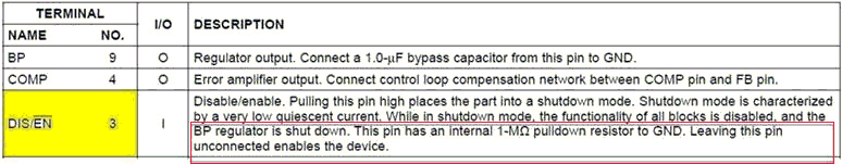
I am having a Power Moding issue with Internal PD 1MOhm on DIS/EN^ pin as the PD means the TPS40210-Q1 will turn on by default when SW PFET is turned on.

However, as soon as SW PFET is on, the Power Supply will take some time to stabilize and MicroP will take some time to initialize (typically in miliseconds).

This means the PD in TPS40210-Q1 will enable the TPS40210-Q1 for a short duration (miliseconds) time.

The SW PFET is used to meet the Quiescent Current requirement stated above and the Schottky Diode are used as Reverse Battery Protection (RBP).

Therefore, I am adding some discrete control circuitries as below (PU resistors, BJT NPN and Zener diode) to ensure TPS40210-Q1 remain OFF till the MicroP is ready, then TPS40210-Q1 can be commanded to turn on through the Base of the NPN transistors. The Zener Diodes are used to clamp the DIS pin voltage to below 10V max rating.

Please help to review the discrete control circuitries below. Thanks in advance.

  • Hello Wilson,

    What is the purpose of the Schottky diodes? Do you need to make sure that no current is sent backwards from the transformers?

    I understand the transistors the way that you want to invert the signals from the MCU, is this correct? If you can invert the signal in the MCU, this is maybe the easier way, then you do not need the transistor. You only need to be sure that the MCU output is high impedance as long as the MCU is not started, because then the resistor from DIS/EN to KL30T_PROT will pull DIS/EN high.

    If I am misunderstanding the issue, please send some scope plots of the supply voltage and DIS/EN voltage that helps me to understand.

  • hi Brigitte,

    As mentioned earlier, the Schottky Diode are used as Reverse Battery Protection (RBP).

    Yes, to block the current flow from Transformer primary coil to KL30T.

    The reason I am using the Transistor NPN is to isolate the Battery voltage from the MicroP output (3.3V logic output).

    It is not encouraged to expose the MicroP output pin to Battery Voltage (12V typical).

    From safety perspective, if the 5.6V Zener failed to clamp, at least the NPN will isolate MicroP output from battery voltage.

    Sorry that I am not able to provide any plots right now, because I don't have any hardware for evaluation.

  • Hello Wilson,

    The circuit you are using on the DIS/EN pin should work. I wonder if a Zener diode alone (as you only need to be above 1.52V on the DIS/EN pin to disable the part) without the NPN would work as well, but for sure with the NPN it is more safe.

  • Hello Brigitte,

    Thanks for the review and comments.

    Really appreciate it.

    regards

    Wilson.