This thread has been locked.

If you have a related question, please click the "Ask a related question" button in the top right corner. The newly created question will be automatically linked to this question.

LM3406: Difference in LED current waveform at PWM rise

Part Number: LM3406

Hi,

I would like to ask you a question about the LM3406.
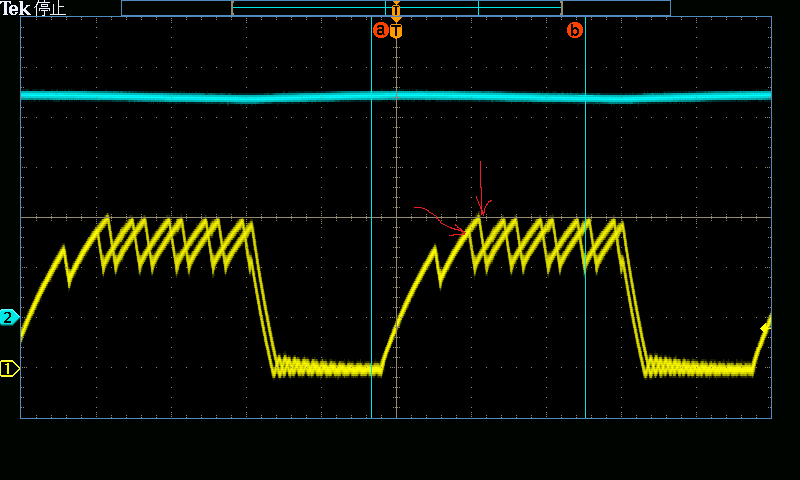
When checking the LED waveform while changing the VIN voltage, two types of LED waveforms are generated as shown in the figure below.
This is the PWM Dimming waveform. Multiple waveforms are recorded in layers.
As shown by the red arrow, the second peak of the inductor current waveform may reach the set value or may have a low peak.
What is the reason for the difference in waveforms like this?
(Normal operation or influence of noise ...)

Best regards,

  • Hello Kaji,

    Thank you so much for your question. We are looking into this, and will get back to you within 24 hours.

    Best Regards,

    Caroline

  • Hello Kaji,

    It looks like you have the scope in persistence mode.  This could easily be just noise on your feedback loop or on Ron from Vin. It is still going to the correct peak current but looks like the frequency might be varying slightly or that the transient response is slightly different due to noise.  On cycle looks like it take slightly longer to reach the peak vs the other.  

    -Francis Houde

  • Hello Kaji,

    Please attach your schematic for us.  The scope capture does not include time base information on it so pleas include that for us.  We are assuming the top waveform is the input voltage is that correct. 

    In general, when you change the input voltage while PWM the current it will change the di/dt of the current and that can causes different ramps timing in the current.

    Thanks Tuan

  • Thank you for your reply.
    I'm sorry, the circuit diagram cannot be published.

    One more point, I would like to ask you a question.

    This phenomenon occurs when the current reaches the set value.
    I presume that this phenomenon does not occur if the logic circuit that determines that the set current value has been reached has hysteresis noise immunity.
    Is it possible to give me your opinion on the above?

    Best regards,

  • Hello Kaji,

    In 8.10 page 11, it's best if you PWM dim at lest an order of magnitude lower than the switching frequency otherwise you can get aliasing and this can be a possible issue here since you are no adhering to this.

    Without seeing your schematic it's hard for me to comment any more on this subject.

    Thanks Tuan