This thread has been locked.

If you have a related question, please click the "Ask a related question" button in the top right corner. The newly created question will be automatically linked to this question.

TPS2373: TPS2373

Part Number: TPS2373
Other Parts Discussed in Thread: PMP20859, TPS2372

Hi,

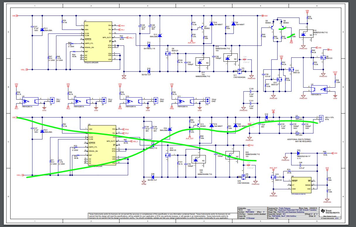
I am using TPS2373 PD - controller into my gateway power supply board. This board have 2 inputs, out of which 1st is POE power supply (55Vdc) and 2nd one is DC-supply (55Vdc).

Issue:

Whenever hot-swap takes place from DC-supply to POE power supply, then output supply of my board always drops to 0V for 2-4 sec. in the mean time PD - controller again negotiates power and recovers output supply while vise versa of hot-swap of power supplies shows no drop of output power supply.

Problem : Because of no standby during hot-swap output load always reboots.

Please, suggest the solution if this behavior (no standby during hot-swap) of PD-controller is not normal.

  • Hello,

    Yes this is normal because the PD and PSE must renegotiate power. 

    You will need to design the board for a smooth transition. Please see the following blog post and the links to the training video and the reference design at the bottom.


    If this post answers your question, please indicate so by marking this thread as resolved. Thank you.


    Regards, 


    Michael P.

    Applications Engineer

    Texas Instruments 

  • Please work with Abhishek 


  • Hi Michael,

       Please have a look at the following table. So, that understanding on the issues could be much clear.

           Power Supply          POE Supply      DC Supply             Output Load

    Condition 1 :                  OFF                OFF                        OFF

    Condition 2 :                  ON                  OFF                        ON (PD Power Negotiation)

    Condition 3 :                  ON                  ON                          ON (DC Supply Serves the Load)

    Condition 4 :                ON                  OFF                        OFF (for 2-4 sec) and then ON (after PD Negotiation)

    Condition 5 :                  ON                 ON                          ON (DC Supply Serves the Load)

    When power supply jumps from condition-3 to condition-4 then, why power renegotiation happened? While in condition-2 PD controller have already negotiated power and later on POE power supply never turned off.

    1. Now please confirm is it the normal behavior?

    2. If this is normal behavior then resources provided by you to Abhishek is about "Dual input redundant POE supply with wall adaptor i.e., PMP20859" but I need smooth transition between only one POE and DC supply.

    Please help!

    Best Regards,

    Rizwan Ali

  • Hello,

    1. Yes this is normal as i previously said. The POE power is not already negotiated. When adapter is connected, the APD pin is high which disables the detection of the PD and turns off the internal hotswap FET. Therefore, the PSE no longer has the MPS signal and cannot reestablish a connection since detection is turned off. Therefore, when the adapter is being used, the PSE is not connected. Therefore, when the adapter is removed, the PSE and PD must renegotiate power. 

    2. The E2E post I gave you is titled " Delivering a smooth transition from AC to PoE power" which is exactly as you need. PMP20859 is dual port AND smooth transition between adapter and PoE. All you need to do is remove the second PoE port. 

    If you read the test report to PMP20859, section 4."Smooth Transition" you would see all the types of transitions possible and the waveforms confirming the behavior. Please read this test report. 


    In the blog is also a training on smooth transition and dual ports. If you watch the video you would see how to do smooth transition, and you could skip the dual port portion. 

    If this post answers your question, please indicate so by marking this thread as resolved. Thank you.


    Regards, 


    Michael P.

    Applications Engineer

    Texas Instruments 

  • Hi Michael,

    Thanks for the valuable feedback.

    Now, please provide me the solution on following points.

    1. We have prepared single POE and DC supply based solution on TPS2373 PD controller IC but resources provided by you is based on TPS2372 PD controller IC. So, do you have any single input POE and DC supply smooth transition solution base on TPS2373 PD Controller IC? If yes, then please share with us.

    2. If no, then please clarify those sections of schematic that need to be removed into your solution i.e., dual input POE with AC wall adaptor. So that, we can make it into single input POE with ac wall adaptor with smooth transition during hot-swap. As its been delayed a lot and we have no time for R&D.

    Kindly help.

    With Regards,

    Rizwan Ali

  • Hello,

    You can use the TPS2373 in the PMP20859 design. 

    As I said, remove the components associated with the second port:

    If this post answers your question, please indicate so by marking this thread as resolved. Thank you.


    Regards, 


    Michael P.

    Applications Engineer

    Texas Instruments 

  • Hi Michael,

    I just add a dummy load of 1mA at POE w.r.t. RTN path and now the issue of standby failure while hot-swap from DC to POE has been resolved.

    Now, I just need to know how much POE dummy load current is required to keep POE active for temperature range is -40*C degree to +70*C?

    Kindly Help.

    Best Regards,

    Rizwan Ali

  • Hello, 

    What you did was add a load so that the PSE sees an MPS signal. That is why a part with AutoMPS is required for the application. However, adding a resistor does not solve all of the challenges of hotswap between AUX and PSE. One of the biggest challenges is the current spike caused by different input voltages on the input bulk capacitor. If your AUX is 48V and the PSE comes in at 57V (within PoE input range), then there is a 9V differential. But since the internal hotswap FET between VSS and RTN is already closed, there is no current limiting by the IC. Therefore, there will be a current spike, and that will eventually damage the part. That is why PMP20859 is the minimal circuitry needed for smooth transition. 

    MPS signal required is 10mA, please find this in the ieee standard. 

    If this post answers your question, please indicate so by marking this thread as resolved. Thank you.


    Regards, 


    Michael P.

    Applications Engineer

    Texas Instruments 

  • Hi Michael,

    Thanks for the reply.

    We are using a Schottky diode just after 10mA dummy load so that all the differential voltage will appear across this diode.

    Please suggest, would it work to avoid current spikes? 

    Can this solution prevent IC damage?

    Kindly help.

    with regards,

    Rizwan Ali

  • No, this will not prevent the  potential damage. The minimum required circuitry is in the PMP20859. 

    If this post answers your question, please indicate so by marking this thread as resolved. Thank you.


    Regards, 


    Michael P.

    Applications Engineer

    Texas Instruments