This thread has been locked.

If you have a related question, please click the "Ask a related question" button in the top right corner. The newly created question will be automatically linked to this question.

BQ25892: battery "simulation" for production test of assembled BQ25892 based PCB

Part Number: BQ25892

We have developed a hardware where the BQ25892 is used to charge a connected battery pack. During production test of the assembled PCB, we would like to verify the battery charging path as well. We use bed-of-needles with an automated test procedure.

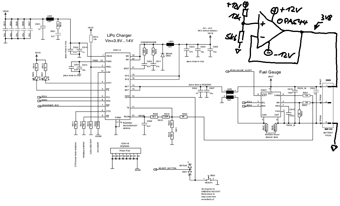
To include a battery pack in the test fixture is no option. On the long term the battery will always be fully charged. So we tried the attempt as described in your application note SLVA618. It looks like the battery simulator is not detected as a battery because there is no current flowing into the charging path and BQ25892 LED indicating charging is not happening. The voltage measured on the BAT+/BAT- pins is 3.8V.

Any idea why the BQ25892 is not starting to send charge current thru the battery simulator?

regards

Michael

  • Michael,

    The BQ25892 does not have battery detection function. It will indicate charging/not charging even when the BAT pin is open if charge is enabled. Please visit https://e2e.ti.com/support/power-management/f/196/t/874557 for BQ2589X: Schematic Review and PCB Layout Design Tips and https://e2e.ti.com/support/power-management/f/196/t/875386 for BQ2589x FAQs. FAQ#1 explains the behavior when the battery is not connected. Please leave the BAT pin open and check if the charger operates as expected first. If the charger operates normally, please check if the battery simulator is really connected to the BAT pin for charging current to flow.

    Thanks,

    Ning.

  • Dear Ning,

    sorry, your answer can not be correct and it seems you did not read my question fully. The BQ25892 has a STAT pin where an LED is connected. This LED blinks when no battery pack is connected. When a battery pack gets connected it is turned on all the time.

    So, the BQ25892 must have some "detection" it should activate its current source. With no battery pack connected, the BAT pin of the BQ25892 also does not drive any voltage! If you hook up a multimeter the voltage is ZERO.

    It also does not help to indicate to use the layout and design tips. The actual PCB works perfect. I was talking about a production test, where you have to verify that a PCB is assembled correctly. This is no layout or schematic issue!!!

    Michael

    P.S. how can I removed the RESOLVED status? It was just clicked by accident. The issue is way from being resolved!! I have attached the relevant schematic part with the battery simulator drawn by hand into.

  • Hi,

    As explained in BQ2589x FAQ#1at https://e2e.ti.com/support/power-management/f/196/t/875386, When battery is not connected,

    1. If charging is enabled by default, the device tries to regulate VBAT to charging voltage (VREG, 4.208V default) then terminate charging. After certain time, VBAT will drop below the recharge threshold and the device charges VBAT to charging voltage (VREG) again. So the charger status indicates between charging in progress and charging complete, so STAT pin blinks.

    2. If charging is disabled with /CE pin or by register bit, the device does not charge and STAT pin should not blink.

    Please note that STAT blinking at 1Hz indicates fault conditions and charge could be suspended as described in 9.2.9.2 Charging Status Indicator (STAT). Could you please double-check?

    Thanks,

    Ning.