This thread has been locked.

If you have a related question, please click the "Ask a related question" button in the top right corner. The newly created question will be automatically linked to this question.

LM317A: LM317 as a current source

Part Number: LM317A
Other Parts Discussed in Thread: LM317,

Hi,

Probably something obvious that I'm not seeing.

I want to use the LM317 as a current source to drive 10mA through a set of resistors and hence set a specific voltage at each resistor junction. My goal is to set the resistor junction voltages relative to the most negative point (i.e. the bottom end of R3).  If I configure the device thus:

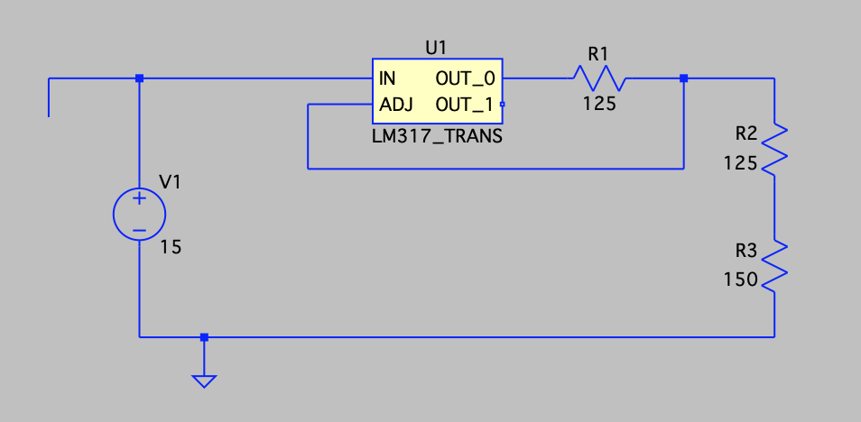
it works fine. The top end of R3 is 1.5V more positive than the lower end and the top end of R2 is 2.75V more positive.  But, if I configure the device thus:

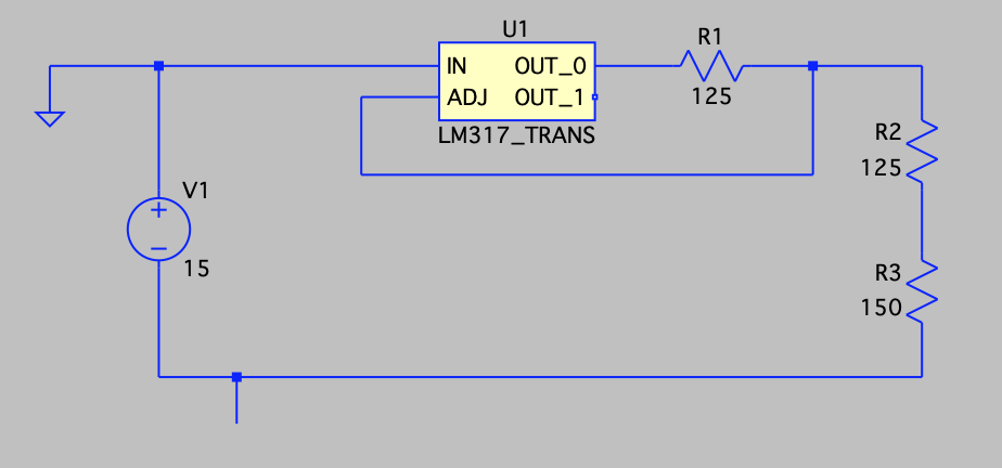
I get very different results. The current is no longer 10mA - more like 37mA - and hence the voltages are way off. 

Why is this? In both cases, the LM317 is seeing exactly the same source voltage - the LM317 doesn't "know" whether one end is a circuit ground or not.

I thought that it was a quirk of the simulator but testing a real circuit gives the same result.

Kind regards,

AC

  • Hi AC, 

    For the configuration with the issue, what is the ground being set up to? You only include a wire in the schematic, and will you provide more details for me to understand why the current becomes to 37mA? 

    Regards, 

    Jason

  • Hi AC, 

    After reviewing the schematic for the 2nd time, I understand the unconnected wire is probably unintended. LM317A is still a positive LDO considering the input needs to see a positive voltage and it's not truly floating. 

    There are a lot of variants of LM317s, and due to the history of the devices, please only use the device according to the recommended configurations listed in the datasheet. Due to the age of the device, it's difficult for us to make confident judgements for any application beyond the applications listed in the datasheet. 

    Regards, 
    Jason Song