This thread has been locked.

If you have a related question, please click the "Ask a related question" button in the top right corner. The newly created question will be automatically linked to this question.

LM1084: Output RC snubber if using film capacitor on output

Part Number: LM1084

Hello,

Several questions that I would be very grateful to have answered:

1) For the LM1084-ADJ, what is the approximate output impedance across the audio band (20Hz-20Khz)

2) The datasheet specifies an electrolytic or tantalum capacitor on the output of the LM1084 as a large enough ESR is necessary for regulator stability. Would an appropriately sized RC snubber in parallel with another low ESR capacitor provide the necessary zero pole at 500khz for regulator stability? If yes, how would I determine the required RC snubber component values?

3) If an RC snubber is not able to provide the necessary zero on the output, what ESR is sufficient for an electrolytic capacitor in order to assure stability? If low ESR electrolytic capacitors are used, is there a formula that allows calculation of the sufficient ESR of the capacitor relative to the capacitance value?

Thanks in advance

  • Hi Mischa, 

    1) For the LM1084-ADJ, what is the approximate output impedance across the audio band (20Hz-20Khz)

    --The output impedance is not a standard datasheet item that we would have in the datasheet. You will need to make the measurements based on the load condition you have. 

    2) The datasheet specifies an electrolytic or tantalum capacitor on the output of the LM1084 as a large enough ESR is necessary for regulator stability. Would an appropriately sized RC snubber in parallel with another low ESR capacitor provide the necessary zero pole at 500khz for regulator stability? If yes, how would I determine the required RC snubber component values?

    --I would not recommend using RC snubber to be in parallel with a ceramic cap to meet the ESR requirement. When a low ESR ceramic capacitor is used, a series resistor needs to be added(no in parallel). 

    3) If an RC snubber is not able to provide the necessary zero on the output, what ESR is sufficient for an electrolytic capacitor in order to assure stability? If low ESR electrolytic capacitors are used, is there a formula that allows calculation of the sufficient ESR of the capacitor relative to the capacitance value?

    --The LM1084 design is done in the 1990s, and most of the LDOs designed 20-30 years ago are mainly working with capacitors with higher ESR than the ceramic ones. The 500KHz is given as an empirical number and I would suggest following the datasheet's recommendation: The recommended load/decoupling capacitance is 10-uF tantalum or a 50-uF aluminum. These values will assure the stability for the majority of applications. For newer LDOs, we have better recommendations/guide on stability and most of them work with ceramic capacitors and the low ESR will result in better AC performance. To verify the stability, I recommend using the load transients method described in this app note

    Regards, 
    Jason Song

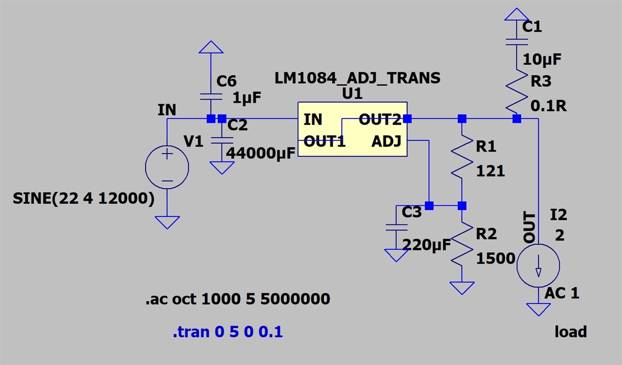
  • Thank you Jason for your response. On the output of the LM1084 I've decided to go with a 10uF film capacitor in series with 0.1R resistor.

    How accurate is the Spice simulation of the LM1084? For the following simulation in LTspice I get an output impedance of ~320 microohms from 20Hz to 20Khz. Is this a reasonable theoretical output impedance from the LM1084 under these conditions (2amp constant draw, 1amp AC)?

  • Hi Mischa, 

    The PSPICE model for LM1084 is highly simplified and is recommended to demonstrate the basic functions of the LDOs.  LM1084 is designed in the 1990s and at that time, there was no modern IC simulator, so our support is also limited. If you are using anything other than the ones that are recommended in the datasheet, to verify the stability, I recommend using the load transients method described in this app note. Hope it helps. 

    Regards, 
    Jason Song