This thread has been locked.

If you have a related question, please click the "Ask a related question" button in the top right corner. The newly created question will be automatically linked to this question.

LM74700-Q1: High-side N-MOS Static Switch Driver

Part Number: LM74700-Q1
Other Parts Discussed in Thread: UCC29002, INA280, LM5069, TPS2492, , LM5060, TPS1663

Hello,

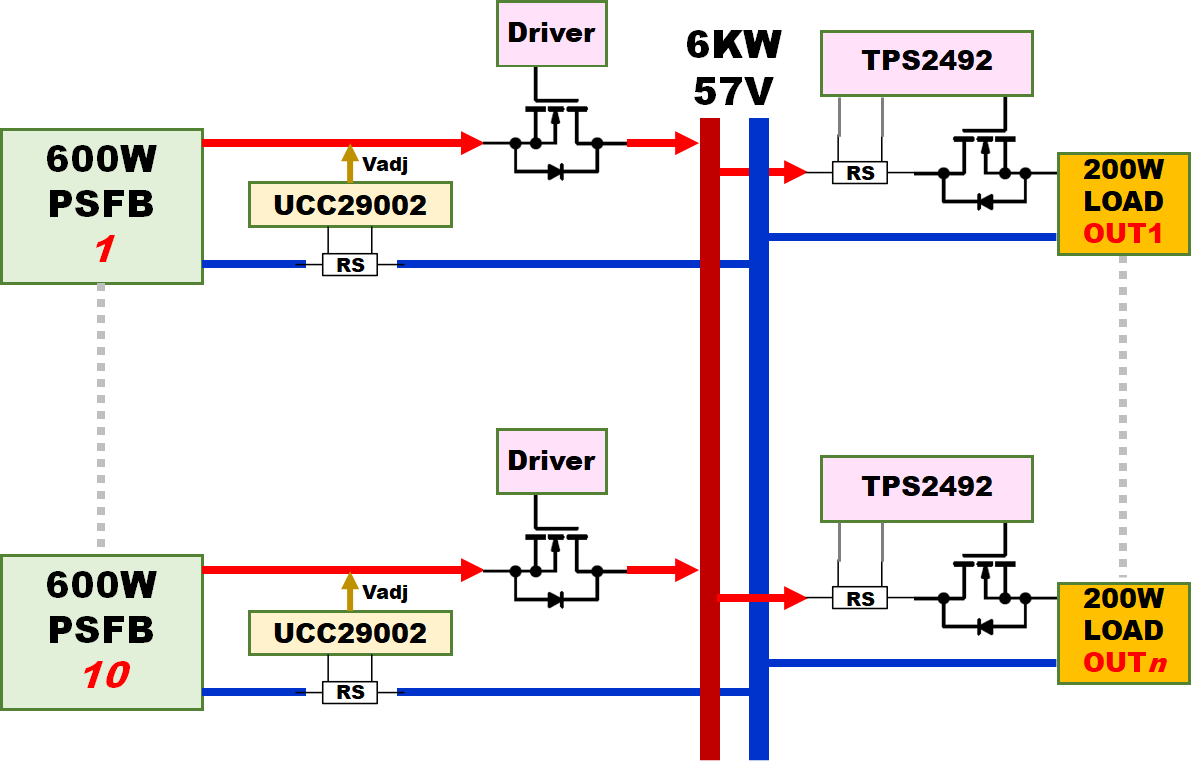
I am looking for High-side NMOS Static Switch Driver. The NMOS FET is used as Ideal Diode for paralleling up to ten 600W PSFB converter modules. A load sharing controller (UCC29002) is sitting on the left side of the FET and implements low side-sensing with V+ only. The output of all converters is aggregated together, forming up to 6KW/57VDC. The power is then distributed into up to 30 OUTPUT connectors to connect various loads.

1) We are considering TPS2492 as an e-fuse with external switch for power distribution to the loads. LM5069 was another option but we need information about the load current and the IMON signal featured by TPS2492 is a plus in this case. Otherwise, we have to use INA280 with LM5069 for current sensing.

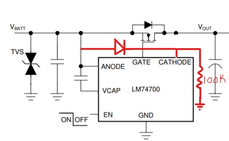
2) We evaluated LM74700-Q1 to be used as a High-side NMOS Static Switch Driver. The issue we encountered is that LM74700-Q1 has a -11mV reverse trip voltage, which is way less than the system regulation accuracy. Additionally, LM74700-Q1 has 0.5usec reverse sensing response, which is much faster than the converter response. Basically, ONLY LM74700-Q1  connected to the converter with the highest output voltage will be active and all the rest will be in the reverse protection mode. One workaround I though about is to trick the IC using a voltage divider between cathode of IC and FET drain to the ground as illustrated in the attached image. However, we are concerned about forcing the IC to allow reverse current, which is not something the IC is intended to do. 

The anode voltage is around 54V. The cathode voltage when paralleling multiple converter with the load sharing controllers active will exceed the the Anode voltage (Vout + Vadj). Vadj = ~2% Vout. Hence, Vc should be < Vout - (0.02xVout). Therefore, R1 > 0.02xR2. R2 is selected to be 200K. R1 was calculated R1 > 4K. Assuming Vout = 54V, Vc is 1.1V below Vout. Maximum reverse current is Im = [(Vout - Vc + Vak_rev) / RdsON] = (54-52.9+0.011)/0.0021 = 529A, which means the IC is no longer limiting any reverse current.

We also considered LM5060 as a High-side NMOS Static Switch Driver, but this IC can't drive a forward switch without having another B2B FET.

Here is an abstract view of a proposed system architecture.

Questions: 

1) PLEASE ADVISE IF TPS2492 WOULD BE AN OPTIMAL CHOISE FOR THIS APPLICATION AND CAN BE USED AS ILLUSTRATED IN ABOVE BLOCK DIAGRAM.

2)  PLEASE ADVICE IF THERE IS A REPLACMENT FOR LM74700 THAT ALLOWS REVERSE CURRENT WHEN THE NMOS SWITCH IS ON. IF NOT, DO YOU SEE ANY ISSUES WITH DC BAIASING THE IC CATHOD TO A VOLTAGE LOWER THAN THE ANODE VOLTAGE? ANY CONCERNS ABOUT RELIABILITY? ANY CONCERNS ABOUT THE ARCHITECTURE? 

THANK YOU!

  • Hi WB, 

    Thanks for considering TI devices and for reaching out!

    1) Is 57V max voltage ? If yes - TPS1663 is another option for TPS2492. 

    If more voltage margin is needed, TPS2492 is optimal choice. 

    2) on LM74700 questions, we will get back shortly.

    Best Regards, Rakesh

  • Hello Rakesh,

    1) 57V is the absolute maximum voltage. The nominal voltage is 48V. The load could be anywhere between 1A and 10A. The 200W is just one case. Therefore, I have to use external FET.

    2) I would appreciate your promote feedback on this point.

    Thank you 

  • Hi WB, 

    Yes, we will work on your questions on LM74700 and get back to you by coming Tuesday.

  • Hi WB, 

    Understood.

    For first-one, please go ahead with TPS2492

    Best Regards, Rakesh

  • I would like to add one more question:

    On the left side of the system, I have a high side switch on the 360V DC bus feeding the 600W PSFB Module as illustrated in the following diagram. The 360V DC BUS is positive grounded supply (-360V). The switch could be placed either on the high-side (0V), QA, or on the low-side (-360V), QB. The diagram shows two just for illustration. Only one of them is needed based on available solutions. 

    The question is: Is there any solution can be used to drive the static switch (QA or QB)?  


  • Hi WB,

    A low side driver from https://www.ti.com/power-management/gate-drivers/low-side-drivers/products.html# product family can be used to drive QA. Let us know if you need help in selecting the driver part. We can forward the request to corresponding product line.

    Best Regards, Rakesh

  • Rakesh.. I will appreciate you help in recommending a solution.

    Couple notes:

    • QA is sitting on the 0V relative to -360VDC. Hence, QA is considered a high-side switch. 
    • There is an AUX PS (12V) to the left of QA sitting on the top of the 0V. However, QA source is on the right side, which will require a PS referenced to QA source or charge pump to drive it.
    • Soft-start is needed to limit the inrush current (charging 390uF) and operate QA in SOA. QA is IPB60R060P7ATMA1.

    Looking forward for your recommendation. 

  • Hi WB, 

    Regarding your question on ORIng + Load Current sharing, you can have a look at Current Sharing in Redundant Systems App note. 

    You can consider using TPS241x instead of LM74700 as TPS241x has programmable reverse current threshold and is suitable for this application. 

    Current Sharing in Redundant Systems (1).pdf

  • I did study this App note before posting my question in here. TPS241x would be a perfect solution if it does work with 48V DC system! 

  • Hi WB,

    You are right. TPS241x can only be used for 12V rails.  Thanks for bringing this up, I overlooked this point.

    Hope you are also aware of the difference between Linear Regulation Control and Hysteretic ON/OFF Control in ORing controllers. If not, please refer to section '6.1 Linear Regulation Control Vs Hysteretic ON/OFF Control' in Basics of Ideal Diodes App note. 

    LM74700 has Linear regulation control which means as the load current reduces the Rdson of the FET is increased to maintain a constant voltage across the FET. This will ensure zero reverse current flow during normal variations in load/Vin. 

    The -11 mV reverse current threshold is helpful during fast reverse current condition.  A fast reverse current condition is detected when the voltage across ANODE and CATHODE pins reduces below –11 mV , resulting in the GATE pin being internally connected to the ANODE pin turning off the external N-channel MOSFET. 

  • Hi ,

    I do understand the difference between Linear Regulation Control and Hysteretic (VOLTAGE) ON/OFF Control. I would not hesitate to adopt TPS241x if it could be used for 48V system. That is why I am trying to see if the disabling the linear regulation on LM74700 as indicated in my first message would be okay. I had raised a very clear question from the beginning and still waiting for an answer. I could also use LM5060 with inrush current limit (soft start) but that will require B2B FETs, which I am trying to avoid. LM5060 doesn't seem to be able to drive forward FET without the a blocking FET B2B. 

    Thx

  • Hi,


    Regarding the reverse current calculations with the circuit you proposed,

    Consider R1 = 4.3k and R2 = 200k, Vanode = 54V, Rdson = 0.0021 ohms

    • The reverse current blocking threshold is -11 mV. For Vc = 54.011 V, the voltage at Vout would be 55.17 V. This would cause a reverse current of 557 A.
      • But remember, this current will flow only during fast transients due to linear regulation control. 
    • For slow variations in Vout, the FET resistance is changed by modulating the gate to achieve  a voltage drop of 20 mV across Anode and Vc.
      • This means for Vout corresponding to Vc (53.980 V) below which the Gate starts to droop and increase the FET resistance is 55.13 V.
      • So, you can consider the reverse current is not restricted during slow variations in Vout for upto Vout = 55.13 which will allow a reverse current of 538.1 A. It is like disabling the reverse current. From your application perspective you need to check if this is acceptable for your system.

    Regarding you below question,

    PLEASE ADVICE IF THERE IS A REPLACMENT FOR LM74700 THAT ALLOWS REVERSE CURRENT WHEN THE NMOS SWITCH IS ON. IF NOT, DO YOU SEE ANY ISSUES WITH DC BAIASING THE IC CATHOD TO A VOLTAGE LOWER THAN THE ANODE VOLTAGE? ANY CONCERNS ABOUT RELIABILITY? ANY CONCERNS ABOUT THE ARCHITECTURE? 

    • Ideal diodes are designed to block reverse current and hence they do not allow reverse current unless we trick them as you did for LM74700.
    • In case you want to allow reverse current when ever the NFET is ON, you can use the below circuit. The NFET is always ON as long as EN is High. In this case you need to have external controller to Enable/Disable the LM74700.
    • Alternatively we are coming up with a part which has does not have reverse current blocking and only has reverse input polarity protection. This part will be released to the market within 2 weeks from now. 
  • Hi,

    Thank you Praveen. That answers my question, indeed.

    - The 20mv drop during gate voltage modulation could reduce a bit the accuracy of the load sharing system. 

    - As for the 100K OHM resistor pulling the Cathode to ground, what is the maximum value I can use in here? I(CATHODE) is couple uA. 

    - Can you please share the preliminary datasheet for the new part? You also can provide me the part number and I will reach out to our local TI rep for more details. 

    Thank you.

  • Hi WB,

    We will be able to share the preliminary datasheet through TI FAE. Can you please reach out to me via TI FAE.

    The 100 kohms is just used to bias the diode. You can select the resistance to GND accordingly.