This thread has been locked.

If you have a related question, please click the "Ask a related question" button in the top right corner. The newly created question will be automatically linked to this question.

TPS22946: OC flag on startup on some circuits but not others

Part Number: TPS22946

Hello, I have a number of circuits using the TPS22946, and I see random startup failures on some but normal operation on others. 

Tried many troubleshooting steps to see if I can get a circuit that fails to start to function properly without success. 

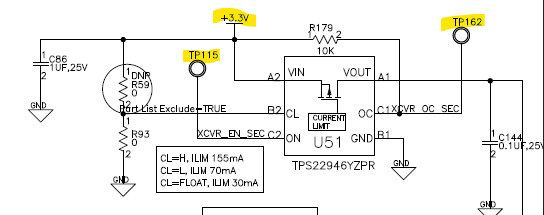
Vin has a 1uf decoupling cap and is connected to a 3.3V rail, EN is controlled by a microcontroller, OC is pulled up to the 3.3V rail with a 10K resistor, CL pin is pulled down to GND with a 0ohm resistor.  Vout has decoupling caps and goes to the VCC of another chip.  This same circuit is replicated multiple times on the same board, and in most cases has no issue on startup.  some circuits fail to start however.  this is concerning and i would like to know if it is a design issue or some other issue (possibly assembly related?)

Here is a schematic of this circuit:


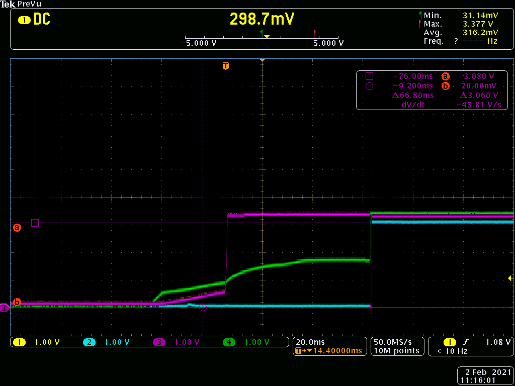
Here is a scope shot of a successful startup:

CH1 is the 3.3V rail, it is covered up by CH3

CH2 is the EN signal

CH3 is the OC signal

CH4 is the Vout

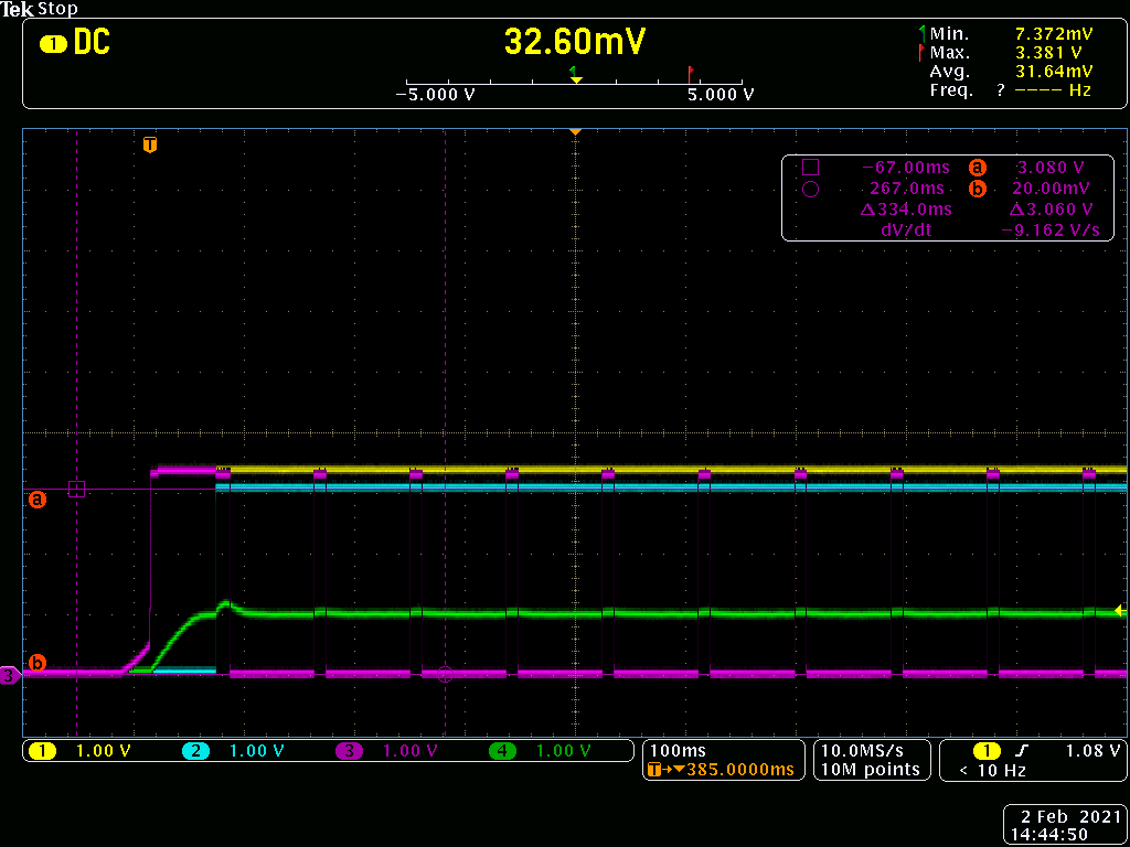
Here is a scope shot of a failed startup:

CH1 is the 3.3V rail, it is covered up by CH3

CH2 is the EN signal

CH3 is the OC signal

CH4 is the Vout

  • Caitlin, 

    Thanks for sharing the scope shots right off the bat

    Also, Could you re-upload the schematic (not copy/paste)? cause its not showing up. Without seeing the schem, I have a few questions about thesetup:

    * Total loading on the output -> You had said there is some other IC on that 3.3V output of tps22946. Are you able to measure the startup current of the whole system, esp between the failing boards and the known working board?

    * Why is VOUT (ch4) rising to 1V before EN high? 

    On those boards which youre seeing the OC tripping, can you try the following modifications and please share the result?

    > Swap the TPS22946 with a fresh one. Is the OC tripping still happening?

    > Tie CL pin HIGH to select the higher current limit 150mA. Is OC tripping still happening on the known bad boards?

    Best

    Dimitri

  • here is the schematic

    I did try changing the CL pin so that it is on the highest current limit setting, no change in the OC flag.

    I am able to measure the startup current on the Rail that is the input to the 3.3V regulator. 

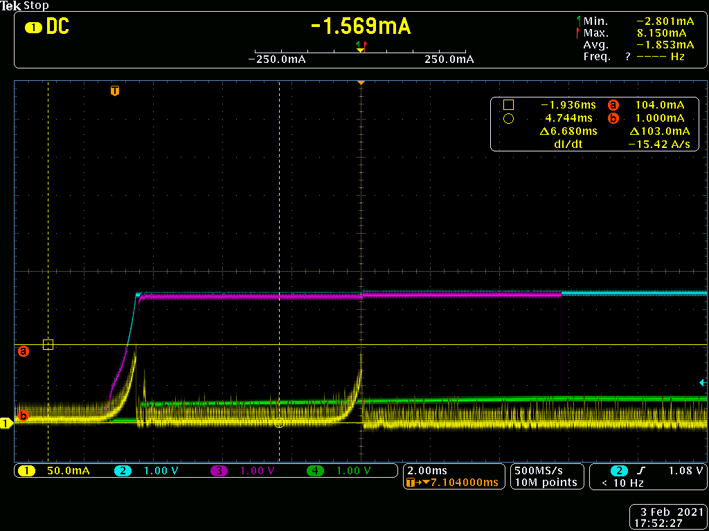
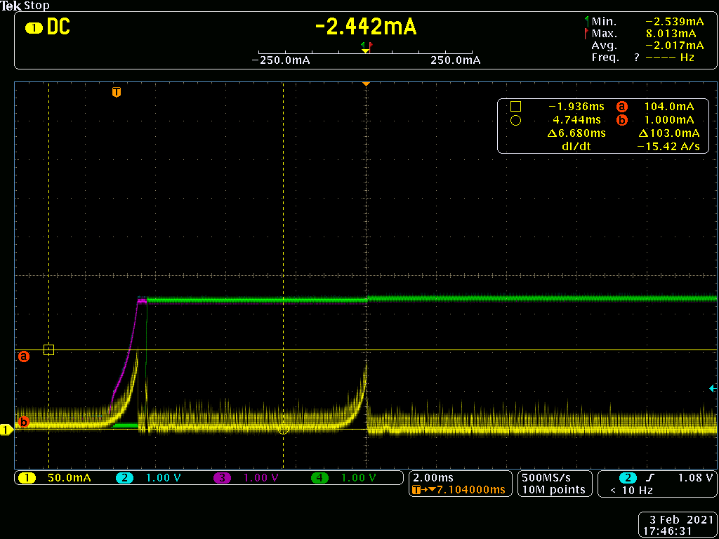
    Here is a scope capture of the startup current on the rail that feeds the 3.3V regulator (CH1 yellow), other probes on the TPS22946 circuit that flags OC on startup - CH2 Blue signal is the 3.3V rail, CH3 purple signal is the OC pin, and CH4 green is the output of the TPS22946.

    and here is a scope capture on the same board, on a TPS22946 circuit that starts normally

    I cannot replace the TPS22946 part myself since it is a small WLCSP part. 

    after getting the current measurements I removed the chip that the VOUT pin goes to (on the failing TPS22946 circuit), essentially eliminating the load or any potential inrush current from this part and still saw the OC flag.  is it possible there is a Head in Pillow or some bad connection under this chip? 

  • Caitlin, 

    Understood on the soldering of WCSP, that is best left to to the machines. lets look at some other things before we start replacing chips. 

    Soldering issues is a possibility but not easy to check without reflowing, replacing the IC or X-ray. 

    In your scope shots, the First one (oc tripping), your VOUT is stuck at 1V, this is indicating to me that there could be a short on VOUT. 

    From your shared current plot, looks like its tripping OC at ~70mA, which is the setting corresponding with CL pin pulled to ground. 

    1) Are you seeing similar inrush current on the known-working boards as well? My question arises because this current of ~70-80mA (hard to tell exact peak), should be tripping on the other boards, as in those, the CL is pulled low for the lowest current limit. 

    2) If you are seeing significantly lower current on the other boards, then its possible there might be something on VOUT, maybe soldering related that is low impedance to ground. From topside view of pkg, blue is VIN and red is GND, maybe a small little solder snake there and is responsible for additional current pull that is above what the others are seeing. I am not sure how likely this is to occur in the wild, especially on several boards unless it is some manufacturing / board construction issue that makes it more likely to happen. 

    3) For those scope shots, just want to confirm that CL was pulled HIGH for the 155mA setting? If yes, its possible that CL pin might be floating and staying at the 70mA setting. 

    Could you do the following debug steps and let me know the results? After this, I think the next step would be to do ABA swap with the IC from the OC trip boards. 

    Tests for Pt 1 -> Bad boards see higher inrush for some reason

    Check startup current on known good boards and compare with the OC tripping boards. Share scope shots comparison of both would be best. 

    Another test for this would be tie a current source to VIN and slowly ramp the current limit on the DCPSU for working/trippping boards to see if there is difference in OC trip current. For this test, would be important to ensure the resistor on CL is exactly same. 

    Tests for Pt 2 -> VOUT has additional low-impedance path to GND which caused extra current. (vout short)

    System Off, Check resistance or continuity test from VOUT to GND on both working and tripping boards. 

    Can also solder a jumper across VIN to VOUT (leaving TPS22946 and compare the turn on waveforms of current. If there is a short underneath TPS22946, we will see the much higher current there, without tripping it. 

    I'd set a reasonable current lim on DCPSU for the above test and if it trips it you have a short there. 

    Test for Pt 3 -> CL floating 

    Remove R59/ R33 on the good boards and bad boards, and probe the CL pin when ON, CL should be ~0.5*VIN, or ~1.65V. This can be compared with the known good boards. 

    If this is not the case, there more likely an issue with CL soldering, please report the voltage in that case. 

    Also, follow up with Resistance/cont check from CL to GND when it is left floating. 

    Best

    Dimitri

    e2e.ti.com/.../976275

  • Hello Dimitri

    These are all good suggestions, I will try them and get back to you with the results.  Thank you!

  • Catilin, 

    Thank you! Will wait for your update. 

    Best

    Dimitri