This thread has been locked.

If you have a related question, please click the "Ask a related question" button in the top right corner. The newly created question will be automatically linked to this question.

BQ79616EVM-021: BQ79616EVM-021

Part Number: BQ79616EVM-021
Other Parts Discussed in Thread: BQ79656-Q1, BQ79616-Q1, BQ75614-Q1, BQ79616, USB2ANY

Thank you for your quick response.

Regarding the user guide provided by your end, I have marked specific places( Page no 6, 7, 8, 14) in the BQ79616-Q1, BQ75614-Q1, BQ79656-Q1 Evaluation Module User's Guide (Rev. B) where I need a bit more clarity.

I need specific information on BQ79616EVM Schematic, Assembly, Layout, and BOM.

In-Page no 15 and page no. 38, I can see U2 ISO7342CQDWRQ1, and IC respectively so it is clear that Automotive,Low-power, Quad-Channel 2/2 Digital Isolator, DW0016B(SOIC-16) is in-built.

So I have some queries:

1. how can I make a daisy-chain connection using this with other BQ79616-Q1 EVM.

-Does it will need external cables? What type of cable or wires recommended?

2. How it will connected to the other EVMs and finally communicate with the PC?

3. How to connect the high side and low side connectors between stacked EVMs device? which kind of wire or cable should be used?

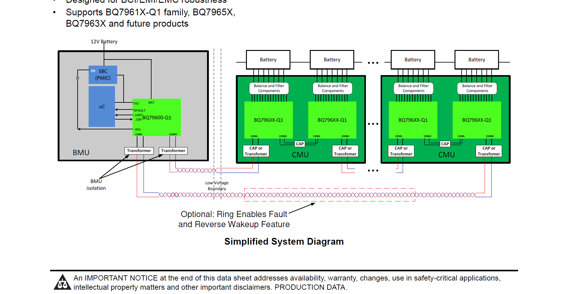
4. On page 7, it is shown in between the connection between COML and COMH there is an isolation component so is it in-built or external?

-If it has to be added externally then what is the hardware or IC to be used?

-What is the capacitive level shifter differential interface between two BQ79616 EVMS?

-Is it in-built or to be added externally? Please specify this hardware component?

-Also specify the physical wire for the optional ring connection? Your response will help us in integrating the stackable BMS for higher voltage battery packs.

Waiting for the reply.

  • Hi Padma,

    1) This question was already responded to. The EVM ships with a daisy chain twisted pair cable which are basic copper wiring.

    2) It connects through twisted pair in question 1)

    3) same as 1) there on connector headers that fit the wire that comes with EVM on either side (COML and COMH). Plugging in to either side of two EVMs will work how they ship if procedures are followed as per user guide closely

    4) Please make sure you closely read over schematic provided in the user guide at the bottom (pg. 18-70). It shows the isolation components that are included on the EVM. The components are also listed in the BOM table. Optional ring connector can be the same type wire as in part 1)

    Regards,

    Taylor

  • Hi Padma,

    Each BQ79616EVM includes a twisted pair cable which can be used to connect multiple EVMs in a stack. You can connect these cables to connectors J10 and J11 on the boards. There is silk screen labeling next to each connector that should help guide your high side/low side connections. 

    The EVMs communicate with each other through a proprietary communication protocol. I'm not able to share more information about this on E2E, but you can find details about this in the IC datasheet.

    The easiest way to connect the stack to your PC is by purchasing a USB2ANY board. The BQ79616 GUI download includes firmware for the USB2ANY board that will handle communication with the BQ79616EVM through UART.

    The BQ79616EVM has external cap and choke isolation populated by default, but if you wish to use other types of isolation (such as cap-only or transformer isolation) there are footprints available on the EVM. Please refer to the IC datasheet for recommended isolation. You can also refer to the schematics in the user's guide, which show the alternate circuits that are not populated. Note that it's not necessary to change any of the hardware on the EVM in order to begin evaluation of the IC. 

    For ring architecture, you can use the same twisted pair cable that's included with the EVMs.

    Best Regards,

  • Thank you for your quick response.

    - I also want to know 12V DC-DC converter is external or onboard? If external, what is the recommended EVM or IC we can use?

    - What is the main use of it?

    Please reply asap as we are going to place an order.

  • Hi Padma,

    We did not mention any use of a 12V DC DC converter so that if that is desired, then we must defer to your judgment on how to place it in the system. Typically power to the device comes directly from the battery pack power.

    Regards,

    Taylor

  • In the system block diagram of BQ76916, 12V DC-DC is shown.  

    What is the EVM for 12 DC-DC and its purpose?  

  • Hi Padma,

    This is a system level block diagram which includes the MCU blocks as well. It is just an example of a full BMS system which could include a 12V DC DC converter to power the MCU/bq79600 from a typical automotive 12V battery but we do not provide a specific requirement for a 12V DC DC to work only with our devices. 

    Regards,

    Taylor

  • Thank you for the quick response.

    In the block diagram, there is a SBC( PMIC ) that is connected to VIO on the BQ79600 board.

    - Please suggest PMIC EVM or IC?

  • Hi Padma,

    This is not required for evaluating the BQ79600 nor the BQ79616. Both EVMs can be powered using just a bench power supply. This is how I do all of my testing with the BQ79600 in the lab. 

    Best Regards,