This thread has been locked.

If you have a related question, please click the "Ask a related question" button in the top right corner. The newly created question will be automatically linked to this question.

TPS54233: EMC noise on TPS54233

Part Number: TPS54233
Other Parts Discussed in Thread: TPS65400

Dear Support,

On our product we use TPS54233 and we see with the near field probe that we detect a lot of noise on this component. All other components are silent. Is this possible that you review the design if you can see any errors in it?

With TPS54233DR we are converting 17.1V-18.9V to 13.30V @ 1A. After conversion, we use second stage buck converter for regulating the current for charging of the battery with 0,9A max. Check the PDF in the attachment for details.

Thank you for your support.

Regards,

Blaz

Documentation_VG_v1.4.1_11012021.pdf

  • Dear support, 

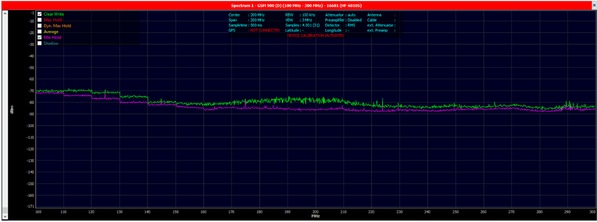
    I have done additional measurements where I have changed the components value on the buck converter according to the values which are calculated with WBDesign. Even if I change them we don't see any change in the noise on the  TPS54233. The only change we see if we use 10uF C1 and C4 capacitors, but in this case also the output charging current drops. We don't know why this happens. 

    In the attachment are measurements we made. 

    Regards, 

    Blaz 

     VyperGo_EMC_U2.docx

    5444.WBDesign3.pdf

  • Hi Blaz,

    I have some questions may need your help:

    1) In your rest results, what does 'max hold' and 'min hold' mean? Is it the limitation or the maximum/minimum value you measure on the TPS54233?

    2)What does the green curve mean?

    3)Are you saying by changing C1/C4, TPS54233 couldn't deliver 1A?If yes, please fix this issue first, C1/C4 should be able to configured as 10uF

    4)Have you tried by disconnecting the second stage buck regulator while only check the TPS54233 performance?

    5)If possible, could you share us layout as well?

  • Dear Vincent,

    My answers below:

    1) In your rest results, what does 'max hold' and 'min hold' mean? Is it the limitation or the maximum/minimum value you measure on the TPS54233?

    Max hold is max measured noise, min hold is No noise line.

    2)What does the green curve mean?

    The green line is the nose of current mesurments whit components and currently described. 

    3)Are you saying by changing C1/C4, TPS54233 couldn't deliver 1A?If yes, please fix this issue first, C1/C4 should be able to configure as 10uF

    Yes, this is how it looks, but I don't understand why. 

    4)Have you tried by disconnecting the second stage buck regulator while only check the TPS54233 performance?

    I am planning to try this today. 

    5)If possible, could you share us layout as well?

    The layout below:2046.Documentation_VG_v1.4.1_11012021.pdf

  • Hi, Blaz 

    It looks the C1 and C4 affect the stability, let's make the IC work more stable first. 

    Comments: 

    1. What is the value of C7 and C10? 

    Suggest changing the compensation circuit same as Webench design. 

    2. For the input capacitors, what is the ESR of C1? 

    Suggest keeping C1, parallel another 2*10uF MLCC for it according to Webench design. 

    3. For the output capacitors, what is the ESR of C4? 

    Suggest changing C4 to 2*10uF MLCC too. 

    After these changes, check if the output current can up to 1A? 

    Some comments for EMI test: 

    1. What is the frequency range that you care about? it is 100MHz to 400MHz, right? 

    2. I didn't see the noise limit in your measurement, could you show it? 

    3. There is EMI case for another device TPS65400, it looks similar with your case. 

    And there is a reference design for your reference. 

    In short, for the 100MHz to 400MHz emission, recommend to add common-mode choke, EMI LC filter, and many small value capacitors at VIN pin, and so on.