This thread has been locked.

If you have a related question, please click the "Ask a related question" button in the top right corner. The newly created question will be automatically linked to this question.

UCC27282-Q1: Full H-Bridge at 100% PWM

Part Number: UCC27282-Q1
Other Parts Discussed in Thread: SN6501, UCC27201, UCC27282

Hi all,

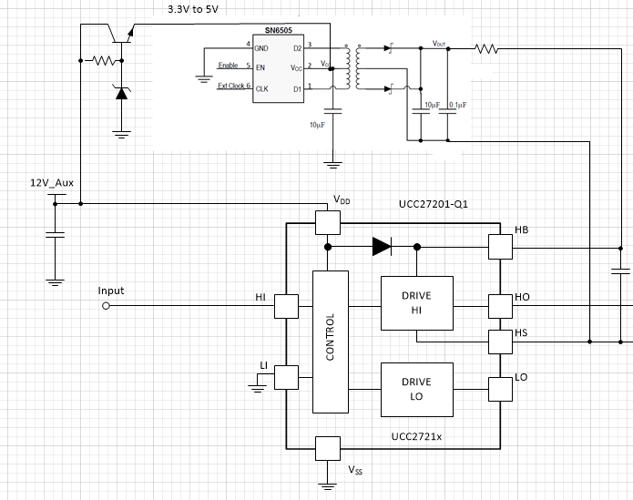
I'm thinking to use two of your UCC27282-Q1 to drive a Full H-Bridge like showed in the following image ( the inductor represents a brushed motor ):

Full H-Bridge Configuration

Is it possible to use a PWM with 100% duty cycle in this configuration? 

Can I keep the High mosfet at level high indefintely, or after some time the boot capacitor discharges and the high mosfet turns off?

In this example I use the low mosfets for choppering, is it better to use the high mosfets?

Regards,

Lorenzo

  • Hello Lorenzo,

    For DC operation of the high side driver, it is not practical to use the bootstrap bias since as you mention, at some time the boot capacitor will discharge and the high side driver will turn off from the UVLO function.

    There are small simple devices from TI, the SN6501 and SN6505 that are designed to generate the floating high side bias to solve your issue. Using a floating high side bias for the HB-HS bias will enable DC operation.

    Confirm I this addresses your questions, or you can post additional questions on this thread.

    Regards,

  • Hi Richard,

    Can you explain a bit better how I should connect your device SN6501 or SN6505 ( or similar as the Vgs on the transistor has to be about 10V ) in my scheme?

    Can you show me an example?

    Regards

    Lorenzo

  • Hello Lorenzo,

    I have a diagram showing an example with the SN6505 and the UCC27201 driver but the connection and configuration will be the same for the UCC27282. For setting the voltage of the floating bias, refer to the SN6501 or SN6505 datasheet for selecting the turns ratio of the transformer which will determine the bias output voltage. Also Wurth and Coilcraft have off the shelf transformers for the SN6501 and SN6505 devices.

    Let me know if you have any trouble seeing the diagram, or if you have more questions you can post additional questions on this thread.

    Regards,

  • Hi Richard,

    Thanks for your clarification.

    If 90% Duty Cicle is accettable, do I need yet the SN6501 or SN6505 or the Full H-Bridge can work without them?

    i.e. if the scenario is the following:

    The motor always runs in the same direction with the transistors driven like follow:

    - Left, High: OFF

    - Left, Low: PWM

    - Right, High: ON

    - Right, Low: OFF

    In this scenario, the Right side of the H-Bridge is DC polarized, so after some time, does the Right Boot Capacitor discharge?

    Is there any trick in the transistors driving in order to avoid the the SN6501 or SN6505?

    Regards,

    Lorenzo

  • Hello Lorenzo,

    If there is some minimum duty cycle of the low side switch, which results in some maximum duty cycle (but not DC) in the high side switch a bootstrap bias can usually be used.

    In the example you show, the right side shows the HO on and LO off which I assume the HO is DC on. in this case the right high side would still have an issue maintaining the HB bias.

    What some designers do, is have a case where there is not DC high side operation, but have a high duty cycle with low duty cycle on the low side switch to allow the boot cap to charge. I think this is a compromise to allow use of the bootstrap bias instead of a dedicated high side bias power supply.

    Confirm if this addresses your question, or you can post additional questions on this thread.

    Regards,