This thread has been locked.

If you have a related question, please click the "Ask a related question" button in the top right corner. The newly created question will be automatically linked to this question.

BQ76952: Sample calibration code example

Other Parts Discussed in Thread: BQ76952EVM, BQ76952, BQ76942, BQSTUDIO, EV2400

Hi Ti expert,

I am facing an issue running the sample calibration code (in python) as mentioned in the " Programmer’s Guide BQ76952, BQ76942 Calibration and OTP Programming Guide " . after executing the script I get an error saying there is no 'bqcomm' module installed. I have searched it online but found no module by the name of bqcomm. how to make this code executable without having this module then? also reagarding my previous query I have some confusion in the steps mentioned. to be able to apply 2.5 V and 4.2V on each cell as mentioned in the guide steps , do I need to apply 40V and 67.2V across the BAT+ and BAT- terminals only ? as the bq76952EVM needs the power to run so how will this work. BAT + and BAT - having a dc supply for eg (12V) and then applying 2.5V per each cell from another supply and each time a press enter in my code (in total16 times for 2.5V and 16 times for 4.2V) ? and then it will print out the cell gains and offset . Am I thinking correctly? All what I have mentioned above is from the smaple code provided at the end of the programmers guide for BQ76942 and BQ76952. As always, thank you for your assistance. 


  • Hi Bilal,

    The Python code is just provided just as an example sequence to show the calibration steps and calculations. The bqcomm library is not available publicly. 

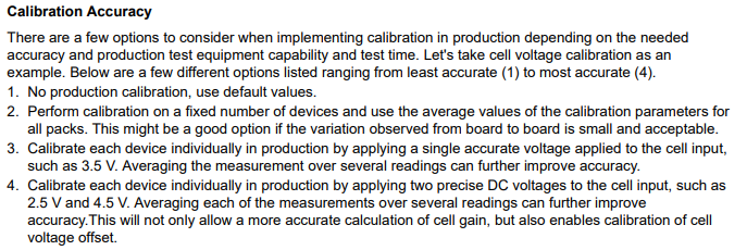
    In Section 2 of the guide, it describes some different options for calibration. The code example covers option #4 in this list which is the two-point calibration. When you calibrate each cell voltage, you need to provide a precise voltage to the specific cell you are calibrating, so using the BAT+/ BAT- terminals only (using a resistor divider) is not going to provide the most accurate calibration because the resistor precision will come into play. 

    Best regards,

    Matt

  • Hi Matt, 

    so if the bqcomm library is not available publically then what other modules can be used as a replacement? as I am not a python expert I am facing trouble running the code mentioned in the guide. yes I read the 4th option already before which is used in this script so just for my curiosity,  as this code says, do I enter 16times as in user input for each time I apply 2.5V and 4.2V for eg in the output of the code? my question here is that as shown in the figure for Host Connection Concept in the User’s Guide BQ76952 Evaluation Module, I have applied some DC voltage across BAT+ and BAT- to power the EVM. now each time should I apply 2.5V and press enter across the respective cell terminals? and after 16times it would calculate gains and offset for me while having a dc voltage across bat + and bat- terminals ? in that case I would need two power supplies one to power the EVM and the other to apply a precise voltage across each of the cells. but how would this sort of scenario work? I mean when I apply 40V across the batt terminals, because of the voltage divider already present I read 2.5V on the BQ software. Can you please explain how can I correctly implement step #4 as you mentioned above as I want to do each cell calibration and also the module which is missing in the code as its not available publically as you mentioned . Please recommend another one that is open source and is compatible with python script. I am a bit confused with the code and the voltage implementation across each cell inputs. Please clarify my doubt kindly.  

    Kind Regards,

    Bilal

  • Hi Bilal,

    Ideally, you could provide 2.5V to all cells simultaneously (this is what I did for this example) and then provide 4.2V to all cells simultaneously. The steps and calculations are described in the guide and the Python example code is going through these steps as an example. The hardware and software for a real production solution would not directly use this example code - you would need to find the most efficient and cost-effective solution for your BMS. 

    There is a BQTools SDK that may be useful for you - you need to reach out to your local TI sales representative to get this. I am not very familiar with the BQTools SDK, but many users use this to help in creating production software. 

    I do not have an open source solution for you to run this specific Python script. As I have said, I provided this as an example of going through the calibration steps provided in the other sections of the guide.

    Best regards,

    Matt

  • Hi Matt, 

    According to your statement above I have understood that you applied 40V across the bat + and - terminals so to reflect 2.5V across each cell. if my thought is wrong then how can you provide 2.5V to all cells simultaneously with having a power supply connected as well to power the EVM, I mean batt+(cell 16) will be already in use for powering the board. 
    about BQtools SDK , is this somewhat a substitute to bqcomm module because as far as what I understand is that it's a module that detects EVM2400 in the code and does a handshake job between the PC and the bq76952 EVM . Am I right ? so if one doesn't have both of these modules than it's not possible to have this evm2400 detection into the code or there are other solutions for this kind of problem too? Moreover, I see that you included "Pywinusb" module in the code but didnt use any function from it , can I know what is it used for ? 

    Kind regards,

    Bilal

  • Hi Bilal,

    We have other hardware internally - this code was not run using the EVM. You can use a resistor divider like the one on the EVM for calibration - but the calibration will only be as accurate as your resistor divider. The device has good cell voltage measurement accuracy without calibration, so you would need accurate voltages to calibrate to improve it further.

    You will not be able to run this example code directly - it is only provided as an example. The BQTools SDK is used to enable PC to EV2400 communication (an EV2400 circuit is included on the BQ76952 EVM). It can be used to create a custom production solution with many of the functions from BQStudio. It does not work directly with this Python example.

    The bqcomm Python library is similar - it allows the used to send I2C commands from the PC to the IC using the EV2400 circuit. You could interface to the I2C with a different tool or with a microcontroller. For example, there are MSP430 code examples in the BQ76952 product folder and one of the examples goes through the same series of commands as the Python script included in the BQ76952 Software Development Guide (https://www.ti.com/lit/an/sluaa11a/sluaa11a.pdf). 

    Ultimately, BQStudio provides a way to do calibration on the EVM in the Calibration tool window. This is a single point calibration. If you want to do a 2-point calibration, you will need to use a microcontroller or another tool to interface to a PC. 

    Best regards,

    Matt

  • Hi Matt, 

    Yes, I have used a microcontroller before to use some I2C basic read-write commands but never used it for calibration purpose. it seems like one can perfrom a similar calibration procedure but using a microcontroller/microprocessor instead as you said above. So are you trying to say that without bqcomm or BQTools SDK one can't have a PC USB to EV2400 communication or there are other solutions possible too?
    I am concerned about doing this on a PC level apart from the microcontroller way as you suggested. Yes, I do understand they dont need calibration usually but I keener to test the host type of calibration and compare the accuracies after a definite time period. also, you didn't told about the use of "Pywinusb" module in your code, what are using it for? 
    Now coming back to your sample code , imagine I just want to use the Voltage divider which is present on the EVM for callibration purpose , instead of applying 2.5V and 4.5V to each cells , would this make sense if I apply 40V and 67.2V on Batt + and - terminals ( considering 16 cells for bq76952 so each cell has 2.5V and 4.2V respectively) and then the code will calculate the individual cells adc counts and eventually the gains and cell voltage off set ? Correct me please  If I am thinking it wrongly and suggest me what changes will I then need to make in the sample code accordingly. My main aim is to get a working piece of code from the example script as provided in the guide. Lastly , I have already tried the calibration tool from the bqsoftware but here by 2-point cal you meant two diff sets of voltages right ? 

    thank you for constant guidance

    Kind regards,
    Bilal

  • Hi Bilal,

    I don't have other solutions available for automation. Using BQStudio, you can go through the steps for calibration using the Command Sequence window. There is some automation possible there - for example, you can execute a series of commands and save it to a file that can be reloaded. I have some examples of using this window in the BQ76952 Software Development Guide. 

    I am not really sure what the "Pywinusb" module is doing - I cannot remember if there was a specific reason this needed to be added. 

    For the example, yes you can apply 40V and 67.2V on the Batt+ and - terminals. This will give approximately 2.5V and 4.2V for each cell. 

    The BQStudio calibration tool (1-point calibration) should do a good job of calibration as well. You could try this method first to see the accuracy. The instructions for using this tool are in the EVM User Guide.

    Best regards,

    Matt

  • Hi Matt,

    So I have edited the sample provided code according to my needs but I am facing issues reading the cells voltage counts (DataRAM_Read fn) . I get "Nack Received" error message for all cells . Also I read fet status to be 0x05 which corresponds to Safety Status B() Command if I understood correctly. Moreover, does the device needs to be in Sealed mode or full access mode to be able to read and write the RAM registers as in the code functions (DataRAM_Read and DataRAM_Write). Could you please go through my code and point out the wrong parameter used (maybe), I am using a microprocessor for the calibration. Can I send you the file in a private message? thank you for your continuous support. 

    Kind Regards,
    Bilal

  • Hi Bilal,

    Sure, you can send the file in a private message. I just sent you an E2E connection request now. 

    If the device is SEALED, you will not be able to read or write to the RAM registers. 

    Best regards,

    Matt

  • Hi Matt , I tried sending you a message but it doesn't allow me for some reason, I also didn't receive any connection request too, Can you try it again please, Thank you

  • Hi Bilal,

    I sent you a private message. Let me know if you see it. In the top right corner of the E2E site there is a message dialog box that should show if you have new messages.

    Thanks,

    Matt