This thread has been locked.

If you have a related question, please click the "Ask a related question" button in the top right corner. The newly created question will be automatically linked to this question.

LM5113: Class D amp with LM5113

Part Number: LM5113

Hi, 

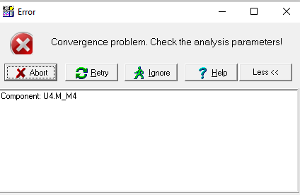
I want to use the LM5113 gate driver to improve the performance of my class d amplifier. My input is a sin wave with frequency 20K and amplitude 2V. I built the circuit based on LM 5113 datasheet. However, when I do my simulation, it always has a convergence problem. Could anyone please tell me how I am able to fix the problem? Thanks a lot. The circuit and the problem is on the attachment. 

Best, 

Zhekun Liu

  • Hello Zhekun,

    Thanks for reaching out.

    The original TINA transient file appears to run as expected from the product folder page.

    Having said that "convergence problems" are generally associated with setting the right "analysis parameters" in "Analysis" folder and ensuring that your input signal is within the transient analysis range.

    Additionally, the comments from my colleague in the earlier thread are also valid for this driver. 

    Regards,

    -Mamadou 

  • Hi Mamdou,

    First of all, I really appreciate your help. I try to find out which part of my circuit is not working. I take off the high and low side MOSFET and test the output voltage of LM5113. I find out that the high output voltage works well but the low output voltage does not work at all. Could you please help me how I should change my circuit. Thanks. 

    Best, 

    Zhekun

  • Hello Zhekun,

    I will further review and get back to before COB Friday.

    Regards,

    -Mamadou 

  • Hi Zhekun, 

    My name is Leslie and I work with Mamadou supporting TI's gate driver products.

    Thanks for sharing the waveforms. I see that the "Vpwm_invert" signal/pulse that goes into the "LI" input of the LM5113 is switching between -5V and 0V. The recommended operating conditions for both LI and HI inputs is from minimum 0V to maximum 14V, therefore a signal from -5V to 0V will not work and in a real circuit it would actually damage the device. Please refer to the device datasheet section 6.3 "Recommended Operating Conditions".

    Best regards,

    Leslie