This thread has been locked.

If you have a related question, please click the "Ask a related question" button in the top right corner. The newly created question will be automatically linked to this question.

UCC27284: UCC27284 This for High Side Battery Switch

Part Number: UCC27284
Other Parts Discussed in Thread: SN6501

Hey,

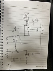
I am trying to use UCC27284 as a high-side battery switch to replace the relay. I have the following questions:- 

1. When making a 48V battery switch for 100A, should I provide isolated power to UCC27284, or can a nonisolated supply also work for the same.
2. for driving the gate above its vth and to operate in saturation region I wanted to understand how will that be done ( do i need a charge pump circuit or can it operate without the same), as I am using this article as a reference so far. (https://www.ti.com/lit/an/snvt010a/snvt010a.pdf?ts=1615367452699&ref_url=https%253A%252F%252Fwww.google.com%252F)

3. Also should I have an active freewheel circuit or a passive one is good enough, a bit worried about the heating of the system. 

Thanks in advance. 

Naman

  • Thank you for the interest in the UCC27284. For a high side DC switch, there does need to be a floating high side bias to provide the HB bias with the HS pin as the floating ground reference.

    The application note with the external floating bias can be used to achieve this.

    There is also a simpler proposal which is shown in the application note below. It is based on a charge pump utilizing one of the driver outputs which results in a low cost external circuit. The application note can be found below.

    https://www.ti.com/lit/an/sluaa58/sluaa58.pdf?ts=1615390731091&ref_url=https%253A%252F%252Fwww.ti.com%252Fproduct%252FUCC27284

    Confirm if this addresses your question, or you can post additional questions on this thread.

    Regards,

  • Hey Richard, 

    Thanks for the answer, I did look at the same. I wanted to know a few things. 

    1. Can I control this circuit with just 3.3V on the Hi,LI side because the truth table in the datasheet does not give me a condition where both HO and LO are high when I provide a constant 3.3V on the input. 
    2. Is there an alternative to this, if I use an isolated Gate driver or isolated supply to drive the gate driver. 

    3. Can you recommend some good comparator which can help me do an active freewheel circuit with Mosfet for the same. 

    Naman 

  • Hello Naman,

    The application note I referred was a different approach than the one you referenced, I wanted to show you an alternative for the high side bias.

    You can control the LI and HI with a 3.3V control signal, and on the UCC27284 you can have LO and HO high at the same time.

    On question 2, the alternative for the high side driver floating bias is in the application note that you provided with the SN6501 based isolated bias supply. Both concepts of the high side driver and bias solution shown in both application notes can work with an isolated driver. You do still need a floating bias for the high side driver whether you use a driver such as the UCC27284 or an isolated driver however.

    For question 3, I am not sure I understand what you mean by an active freewheel circuit, can you show a diagram or link showing this circuit or concept. I am sure TI will have a good comparator solution.

    Regards,

  • Hey, 

    Thanks again for answering my questions. 

    Let me show you a basic block diagram of the circuit which also addresses an active flywheel system that I read online.

    One of the doubts that comes to my mind is when I connect the gate driver with a 48V system I would need 48V +10V at my gate for NMOS to be completely saturated and that's where I am getting confused and have been asking you the questions so if I do a floating Bias I think that will solve my doubt in a simulation too and if you can share more information on the floating bias that would be great. 

  • Hey Richard, 

    Also, I was looking at other circuits and came across LTC7001 which is quite a simpler solution to implement does TI has a similar but cheaper solution that I can implement. 

    Naman

  • Hello Naman,

    Regarding the gate driver and high side floating bias, the application note that you initially referenced using the SN6501 device for the floating bias will work and also the application note I provided with the charge pump will also work for the high side bias.

    To determine which one is best, will depend on the switching frequency you need to operate the high side switch. If the switching frequency is low, or more of an on/off operation both the charge pump and the SN6501 bias will work. If the switching frequency is over 100Hz I would suggest the SN6501 bias solution as this can work with higher frequencies, even in power converters.

    For the more integrates solutions, there are devices in other product families with more integration. The best way to find the products is go to ti.com and search on high side switch, or high side load switch.

    Confirm if this addresses your questions, or you can post additional questions on this thread.

    Regards,