This thread has been locked.

If you have a related question, please click the "Ask a related question" button in the top right corner. The newly created question will be automatically linked to this question.

LM46001: Failure in ability to power LDO from VIN

Part Number: LM46001
Other Parts Discussed in Thread: LM46000,

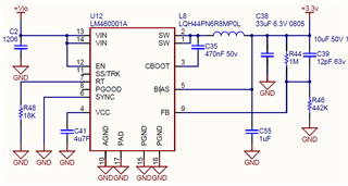
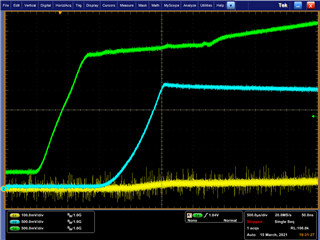
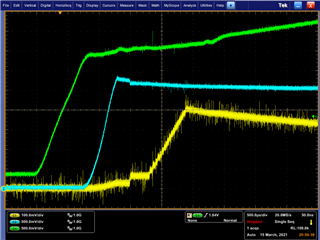
We have an a few percent of boards failing in the field in the same way as described in the related thread.  It appears that the ability for VIN to provide the initial voltage to the LDO  in broken.  If we provide 3.3v to VCC momentarily the device starts and then functions as normal.   Our application is 24v down to 3.3v with around 400ma load. The 24v is derived from an LM46000 operating from 48v.  We have checked that Vout > Vin during shutdown and we do not believe BIAS can be > 30v nor VIN > 65  volts.  Since the previous question is marked resolved do you please have a likely candidate for this failure mode.

Thank you.

  • Hi Simon, 

    It looks like you are setting the switching frequency at 2MHz for the 24V to 3.3V conversion.

    I believe this frequency is too high for this conversion, given the minimum Ton time of the part. Please check equation 6 on page 21 of the datasheet. 

    You should update the switching frequency and component values to cover this conversion range. You can use webench to get initial BOM component values for this design and update the corresponding components (Rt, L, Cin, Cout) in your design. 

    Let us know if this improves the operation. 

    Cheers, 
    Denislav

  • Hi Denislav

    Thanks for the feedback , I appreciate that the switching frequency is not optimum and I will change it on future production.  However my question is about a specific failure mode that has also been experienced by other users in the related thread.

    I would be grateful if you could address the issue of the damage that prevents the LDO from receiving its supply from VIN.  This fault has occurred to around 5 units in 500 over a period of 2 years.  The other 495 are still working ok.

    We suspect something in the system is the cause but we need to understand the vulnerabilities of the LM46001 to figure it out.

    Many Thanks

    Simon

  • Hi Simon, 

    Could you provide oscilloscope waveforms of the VIN and VCC voltage when this happens? 

    It sounds like you are jump-starting VCC with external voltage to make the part recover? Does it recover if BIAS is disconnected from VOUT?

    This should help us debug further.

    Cheers, 
    Denislav

  • Hi Denislav

    Please standby for the results of the tests you have asked for.

    Yes I believe your assertion is correct , normally with BIAS connected to VOUT the LDO runs off VIN until the voltage at BIAS is high enough , then it changes over.

    In our damaged device this does not happen until we provide VCC with 3.3v.  Once started we have not found a limit of how long the device will run.  We suspect it is  is until VIN is removed. 

    Cheers

    Simon

  • Hello Simon,

    I am in Denislav's team and will assist him with the debug.

    Just responding to let you know that we will be waiting to review the data.

  • Hi

    How can I upload a screen shot ?

    Cheers

    Simon

  • There is an insert buttom in post window. You can then select image.

  • Hi Marshall

    Please find the traces you requested both with BIAS connected to VOUT (left)  and BIAS connected to 0v (right)

    Green = 24v VIN, Blue =VCC and Yellow = VOUT

    I am keen to understand what part of the device has failed and hence what external conditions could be the cause.

    Cheers

    Simon

  • It seems in both cases the device VCC is getting power from VIN as in the left case, vout=vbias is below vbias,rising-vhys and in the right case, bias is ground.

    It seems in both cases the output is below set point.

    From the above waveforms, it does not seem to demonstrate device inability to power from Vin?

    It does seem that device is not regulating...would you like me to review the schematic for stability concern?

  • Hi Marshall

    I do not understand your answer, sure there is some feed through of voltage but it is clearly not taking VCC past the UVLO (3.14 volts )  so the device is not starting up.  Until VCC goes above UVLO nothing can happen. 

    Cheers

    Simon

  • Hello Simon,

    Sorry, I misread. I see VCC sitting at ~2.5V or so.

    Can you share any additional information on what is connected to Vout?

    Do you have any belief that something might be back powering the device or causing the absmax on vbias to be violated?

    TI might need to request a quality analysis be done on these units if we find nothing wrong with your schematic.

    It seems that LDO has become damaged in this unit.

  • Hi Marshall

    No worries , yes I agree the part has become damaged.  I read somewhere else that VOUT > VIN can be a problem so i have done some tests on the board and have not found that to be an issue.  It seems to me the candidates are VIN and BIAS but they have a tolerance of 65v and 30v which are both much higher than voltages present.  I was hoping you might be able to narrow it down  by understanding which part of the internals has blown and hence which pin we should concentrate on.

    The 3.3v powers a PIC through a diode and 3 TMS320 processors.

    Cheers

    Simon

  • My gut reaction would be the bias pin.

    You can do an impedance check...A-B comparison between control and fail.

    If failure did occur, it may not necessarily be evident at the pin.

  • Can you share a block diagram of this part of the chip so we identify the likely failed component and hence failure mechanism please.

  • Hello Simon,

    The block diagram contained in the datasheet is the most detailed diagram over public forum.

    Please contact your local TI sales agent if you would like to have failure analysis performed on the device.

  • Edit: Request failure analysis.

  • Hi Marshall

    I am going to send a couple of devices for failure analysis.

    Thanks for your help.

    Simon