This thread has been locked.

If you have a related question, please click the "Ask a related question" button in the top right corner. The newly created question will be automatically linked to this question.

LM5176-Q1: 4 parallel control in LM5176

Part Number: LM5176-Q1
Other Parts Discussed in Thread: LM5176, LM5170, LM5175

Dear Expert:

Base on some reasons, we will replace LM5170 by LM5176 for 3kw DC/DC converter. So far, it is 4phase with LM5170. (48V~30Vin, 48Vout)

Do you have any experience about 4 parallel LM5176? 

I have read the application in TI web site. (Two parallel, SNVA792 and SNVA794).

We want to know whether LM5176 can be controlled by DSP in parallel.

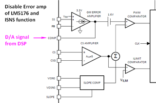
1) Disable Error amp of LM5176.

2) Short ISNS function

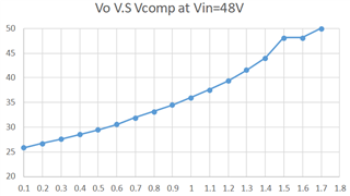
3) Give D/A signal to the comp pin of each LM5176.

Is there any sign impact? Or we shall follow SNVA792 and SNVA794 method?

Thanks.

Aska

  • Hello Aska,

    No, I do not have experience with 4 LM5176 in parallel. I just want to mention that we are normally recommending the device for up to 300W. I wonder if the power dissipation in the driver would cause issues with such high output power per device (750W per device).

    BTW, are you using 2 or 4 LM5170? In contrast to LM5170, LM5176 is single phase per IC and does not support regulation on the input side

    In general I think that controlling according your suggestion should work. The point that I would check in detail is the startup as your control signal would need to be applied before the LM5176 is enabled, otherwise the device would run free and most probable the output voltage would get way too high.

    I did not test this up to now, but normally a DSP should be fast enough and accurate enough to control the converters, I expect.

    You need to check as well if there is negative current on one of the devices, as the converter is able to drive current backwards and you for sure do not want that the converters play with each other without delivering current to the output.

    Best regards,
    Brigitte

  • Dear Brigitte:

    Appreciated your comment and answer your question first.

    Answer: There are 2 LM5170 (4-phase) for 3KW. Yesterday, I tested LM5176 around 48Vo/10A in my current board (1phase for 5A design). But I am not check the thermal for LM5176. The output watt is around 480W higher than 300W you mean. One time LM5176 is broken during 480W testing. I only put the heatsink on MOSFET, not LM5176. I guess LM5176 shall be damaged by heat.

    Question: If LM5176 is run on 750W per phase, is it right direction? Or it shall be lower? 

    I am not really understand how to disable it. That just is our assumption.

    1) Could you please explain it more detail? FB short to Gnd directly or thru 10k. How about SS pin? 

    2) What is COMP input range to control? Does the comp pin control by D/A signal? (I saw there is 1.6V in series path.)

    3) If disable FB function, may I put the external compensation as below picture? 

    4) About your mention "negative current", is it sign impact while LM5176 disable FB/ISNS function? Is there any fixed way? 

    Thank you very much.

    Aska

  • Forgot to answer: I only consider one direction (no regulation on input side.) We didn't apply LM5170 bi-direction. Thanks. 

  • Hello Aska,

    All answers that I am giving are based on theory and not tested, so please check in your 1-phase design first.

    It is strange to me that the device shall be damaged due to temperature as it has a thermal shutdown if it overheats. So I think the damage happened due to something else, e.g. switch node or GND parasitics causing overvoltage or undervoltage.

    The power limit is more given by the available transistors and the driver capability of the device. So you could drive 750W per phase, but most probable the internal drivers will not be able to deliver enough current for the MOSFETs to turn on fast.

    You can disable the device by using the EN/UVLO pin.

    1) FB to GND or through 10k: both is possible as it is a high-impedance input, I would add a cap to the SS pin as normal usage.

    2) You can check this on your circuit when the loop is still closed. Please make sure that you stay in the abs max rating range.

    3) Sorry, but the picture did not come through. Nevertheless, if you do not use the error amplifier, you do not need to compensate it in general.

    4) In closed loop operation, the device will push back current into the input when the output voltage is higher than it should be. I do not know how the device will work if you close the loop through COMP instead of the FB node. You need to control the COMP accordingly to prevent it, I think. The device does not have a DCM function, so this can happen. If you want to use a device that has a DCM then you might have a look at the predecessor LM5175.

    Best regards,
    Brigitte

  • Dear Brigitte:

    Finally, I found the relationship between Vcomp and Vout for LM5176 with disable error amplifier.

    Vcomp> 1.6V, the LM5176 is operating in boost mode. It need be careful the Vin is high level (48V or higher) during Vcomp>1.6V. 

    But the problem is how to transfer in buck / buck-boost / boost mode.

    We are studying this whether it is ok or not for this idea.

    Appreciated your help.

    Aska