Other Parts Discussed in Thread: TPS54160,
Hi everyone,
I have a circuit with TPS54160 and it supplies about 1.2A continuous.
It's beeping and I checked the compensate components with TPS54x60CALCTOOL but I can't.
Please tell me where I'm wrong.
This thread has been locked.
If you have a related question, please click the "Ask a related question" button in the top right corner. The newly created question will be automatically linked to this question.
Hello,
I noted a very large inudctance in your input path that is not damped.
Is your input oscillating?
Regardless, you will need to damp the EMI filter with these simple calcs: https://www.ti.com/lit/an/snva538/snva538.pdf?ts=1615913921397&ref_url=https%253A%252F%252Fwww.google.com%252F
Did I read correctly that you have confirmed device comp values and stability with design calculator?
I tested this circuit in BCI 400Mhz, there is no problem with large input inductance.
When supplied constant voltage with SPMS, not oscillating, It always beeps. I think compensation components are not right.
I changed R7 with 10K then it doesn't beep but I need to know how to calculate it rightly.
According to TPS54x60 CALC TOOL, I should use R7 - 52.3K, C18 - 10pF, and C17 - 47nF, but it didn't work.
Also, there is a step-up converter supplied with TPS54160A, may this beeping be caused by this step-up?
Hello Gokhan, It might be good to try to start ruling things out by apply power right at buck input.
Allow me to dig deeper into the compensation for this design.
Can you please specify the power conditions under which you are evaluating?
Buck input voltage is 12V, the output is 5V 1.2A,
Max. Boost Converter Output is 9.6V, 0.5A.
Hello Gokhan,
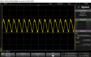
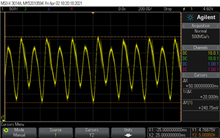
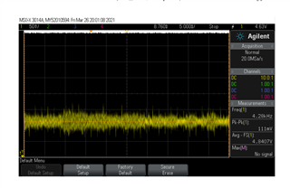
Could you do a couple load transients on the DC/DC and share vout and iout waveform? (vout will also work) I would like to evaluate the stability of the converter by looking at the response on vout.
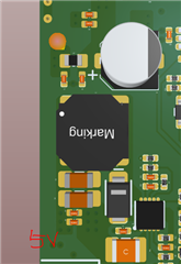
In addition, after discussion with some other engineers, there is belief that the PCB and the components have abilility to generate noise possibly thru vibration. I have a gut feeling the inductors could be a culprit.
Have you pin pointed an area on the PCB that the noise is being generated?
I have heard people have experienced this issued in light load (PFM) condition often. Does this change with power/loading conditions?
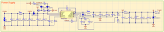
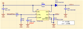
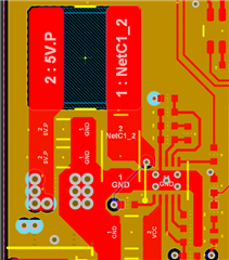
I'll capture the Vout for you. The beeping sound level changes depending on supplied current. I know this because connected different LCDs that need a lower current than the beeping sound levels are low. I attached the layout of DCDC. I don't think it is affected by noise because there are no other sources of noise other than the step-up circuit.
Ok thanks.
If we find the converter to be stable, you might want to consider molded inductors. I am unsure if you already have molded inductor?
I see. Let me know how the transient plots look. Besides converter stability and inductor selection, I might be at a loss here.
Please share oscilloscope captures (.jpg/png).
Supplying raw data makes my analysis more difficult.
Thank you.
Thank you.
I hate to do this to you, but could you share the files as ZIP?
The company does not allow for third-party software to extract .rar
Thanks.
Where is the 0 point on the oscilloscope channel? It seems like a lot of these measurements are clipped.
The reference point is evident in the startup images.
Also, I focused on the voltage difference peak to peak in the continuous image.
With 72K3, DCDC is ringing as can be seen.
Please let me know which captures you would like me to review. The attached screenshot does not have cursor on the screen.
Please let me know which measurements you would like to see? Tomorrow, I will be able to capture them for you.
I just want to see a few transient plots.
Say at nominal input votlage, perform a fast transient (as fast as eload allows for) from mid load to full load.
Also, could you try pressing down on the inductor to see if the noise changes? I have heard increasing the physical inductor size allows for some additional damping off the noise in general.
Please see below FAQ from inductor manf webpage.
Hi, I have tried pressing down on the inductor, it doesn't work.
I hope new images work. First image is for 0.75A, other for 1.4A.
I recommend the BOM to be evaluated over again and confirm with PCB or TI EVM.
With the output ripple alone, at 1.4A load current, their is no true periodicity to the waveform.