This thread has been locked.

If you have a related question, please click the "Ask a related question" button in the top right corner. The newly created question will be automatically linked to this question.

BQ76200: Could BQ76200 meet the following requirements

Part Number: BQ76200

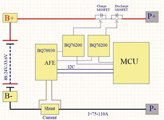
The customer uses BQ76200 to drive the battery charge and discharge, with the maximum continuous current of 110A.

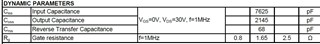
The customer charges in parallel with 11 MOS tubes for discharging, and 11 MOS tubes are used for discharging.The specifications of the MOS tube are as follows.The customer is concerned that the time of shutting off the MOS tube for a single BQ76200 is not fast enough during the over-current protection, and the shutdown time should be less than 50us during the over-current protection.The customer's thinking was that the drive capability of a single BQ76200 might not be able to reach that high speed.Therefore, the customer uses two BQ76200 to drive the charging and discharging MOS tubes respectively.

Now I would like to ask you a few questions:

1. Whether a single BQ76200 can meet the requirement that the tur-off time is less than 50us in the case of over-current protection;

2. If a single BQ76200 cannot meet the requirements of overcurrent protection and the tur-off time is less than 50us, can two BQ76200 be used to drive the realization?How to achieve this?Or is there a better solution?

  • Hi Gabriel,

    It is hard to know if the BQ76200 will meet the desired speed.  You might compare the results shown in https://www.ti.com/lit/pdf/slva729 with the combined load for the customer FETs.  Their Ciss is slightly smaller and they have 1 fewer FET, so figure 34 may be comparable.  

    With the topology shown each BQ76200 has to drive only DSG or CHG.  This will be most significant for turn on where the charge pump has limited capacity to charge the gate capacitance of the combined FETs.  The drivers still have the internal resistances for turn on and turn off.  A lot of the turn off time is spent transitioning the gate from the VFETON voltage of around 10 or 11V to the Vgs region where it turns off.  In the figure 34 above a lot of the 126 us indicated is transition time, the actual current cutoff for the BATT+ to spike and return to normal may be in the 50 us range.  Figure 31 shows 0 ohm in the DSG path which may not be best in a real system implementation.   For a faster turn off it may be possible to use a PNP for a local current loop such as figure 13 of www.ti.com/lit/slua618. I have not tried it with the BQ76200.

    You might see the response in this post for a similar inquiry for additional comment

    https://e2e.ti.com/support/power-management/f/power-management-forum/986481/bq76200-bq76200-drive-110a-current-problem