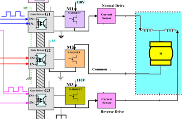
As shown in below diagram, Motor is driven in Normal direction by turning M1 and M2 ON with the help of gate drivers G1 and G2 respectively. I have been using the gate driver IC UCC5390EC.
Gate driver G2 ground pin is connected to source pin of the MOSFET M2 to drive it properly. 110 V supply ground is also connected to the source of M2 to sink the current of the motor. In diagram, it has shown as a one ground as they made common.
Issue: Now I have removed the link between ground pin of G2 and Source pin of M2, but source pin of M2 is still connected to 110 V supply ground. In this scenario, the MOSFET M2 is ON without G2 intervention and when I switch ON only M1 the motor is being driven. Which is undesirable. Please do suggest a solution. Is there any need of miller clamp protection at gate pin of M2?