This thread has been locked.

If you have a related question, please click the "Ask a related question" button in the top right corner. The newly created question will be automatically linked to this question.

UCC5390: False turn ON of the MOSFET under Vgs absence

Part Number: UCC5390

As shown in below diagram, Motor is driven in Normal direction by turning M1 and M2 ON with the help of gate drivers G1 and G2 respectively. I have been using the gate driver IC UCC5390EC.

Gate driver G2 ground pin is connected to source pin of the MOSFET M2 to drive it properly. 110 V supply ground is also connected to the source of M2 to sink the current of the motor. In diagram, it has shown as a one ground as they made common.

Issue: Now I have removed the link between ground pin of G2 and Source pin of M2, but source pin of M2 is still connected to 110 V supply ground. In this scenario, the MOSFET M2 is ON without G2 intervention and when I switch ON only M1 the motor is being driven. Which is undesirable. Please do suggest a solution. Is there any need of miller clamp protection at gate pin of M2?
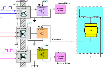
  • Using a single rail supply for UCC5390EC and VEE2 is connected to GND2.

  • Lingamurthy, 

    I do not understand the reason to disconnect GND2 of your middle gate driver  from the source of M2. The gate driver needs this connection in order to properly bias the gate. If GND2 of the driver is left floating, it cannot bias the gate. Thus, VGS and operation of the FET are completely uncontrolled now. 

    In order to control the FET, you must connect Source back to GND2. Also, please share with me the reason that you would want to remove that ground connection? 

    Best

    Dimitri

  • Hi Dimitri,

    Thanks for reply. My requirement is that a single point failure should not result in driving the motor. When I try to simulate the aforesaid failure, I have observed this scenario. Need to address this. 

    Regards,

    Lingamurthy.

  • Hi Lingamurthy,

    Our gate drivers would essentially be left floating without the GND2 reference connection to the source of the M2 fet. Without the GND2 connection, our drivers will not work and the gate of the M2 fet will be uncontrolled.

    To address this issue a solution would have to be implemented independent of the the gate driver. For example you can put a pull down resistor from the gate to source of the M2 fet to ensure the gate is pulled to the source if only the gate driver GND2 pin is disconnected from the M2 source. The resistor would have to remain connected from gate to source of the M2 fet to effectively pull down the gate (VGS = 0V). The solution would depend on the failure you'd be expecting in the system. The gate driver cannot address this without the GND2 pin of the gate driver being referenced to the M2 source.

    Best regards,

    Andy Robles