Hi TI Team,
I have designed a charger circuit around BQ25302.
Schematic:
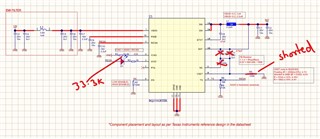
Observation:
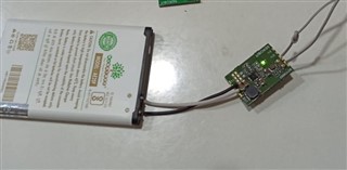
The output voltage is set to 4.2V and a single-cell phone battery is connected
Input Voltage is kept at 5.4V DC
I am seeing charging getting stopped, input current becomes zero after a few minutes of charging.
Like it starts with 420mA current then it reaches 350 or so, then it stops, and after random seconds or minutes, it comes back again for a few seconds and then switches OFF.
When it becomes OFF, the output voltage is 4.079V
and when it starts again, it shows 4.193V @ roughly 353mA
What could be the reason for such a behavior?
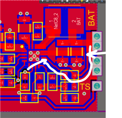
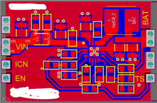
Please review my PCB layout as well:

Thank you.