This thread has been locked.

If you have a related question, please click the "Ask a related question" button in the top right corner. The newly created question will be automatically linked to this question.

LM5127-Q1: LM5127-Q1 Triple Buck Converter or Pre Boost Converter and 2 independent buck converter issue

Part Number: LM5127-Q1

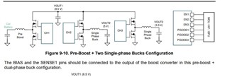
I want to use this PMIC is that LM5127-Q1 for our infataiment cluster. Our clusters are used for Truck. And truck battery voltage is typically 24V.(18V-32V range) But I want to get three output voltage from 24 V is that 12V, 5V and 3.3V. At the attechment, the car battery şs applied to pre-boost, and Vout1 is 8.5V. In normally, the car battery is 12V. How is this used channel 1 as a boost ?

And second quesiton is ;

In the eval board, VIN is 3V to 18V. Vout is =6,9V. But configuration is boost. If I change the only config pin resistor. Can I use this as a buck. But buck converter topology is different. Or this boost converter acceptable for only 3V-6,9V. Can you explain to us ?

If I use this controller for our truck (Vin=24V) cluster. Which topology I  must use this controller ? 

Thank you,

Best Regards,
  • Hi Samet,

    Thank you for considering the LM5127 in your design.

    Regarding your first question: the first channel is a boost to cope with the battery cold cranking such that the two bucks can still have adequate input voltage to work with.

    Regarding your second question, it is mentioned in the datasheet that the 1st channel can also be configured as a buck.  If you change the CONFIG pin setting per datasheet instructions, the EVM's boost channel becomes a buck channel, and you should also need to swap the input and output ports for the channel.  You may need to play with the feedback resistor divider to adjust the output voltage setting point.

    Hope this clarifies. 

    Thanks,

    Youhao Xi, Applications Engineering

  • I understand. Thank you for your support