This thread has been locked.

If you have a related question, please click the "Ask a related question" button in the top right corner. The newly created question will be automatically linked to this question.

TPS2116: How to prevent current going to battery from Main Voltage Source

Part Number: TPS2116

Hello,

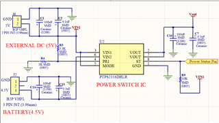
We have tested TPS2116 IC, switching works as expected, and Ultra low current consumption. Our Schematic for testing is attached. V1 is our primary 5V DC Mains , and V2 is our secondary dry cell bettery (3 x AA = 4.5V-4.8V), When V1 off, system is shifted to V2, and if V1 on again, then system shifts to V1. There is one notice case that when V1 Switch from off state to on states, there is a voltage drop on V2 (Here V2, Battery is disconnected (open connection)) of about 100-200mV. and then after some time it slowly downs to Zero. And when V1 and V2 both are connected, then there is a current flow of about 0.1uA - 0.2uA, going into the battery . As mentioned earlier our battery is dry cell type non rechargeable, then this may create issue in future. Please guide us to solve this problem.

Thank You

  • Hi Dipak,

    It looks like your major concern is what we would refer to as reverse current blocking leakage, or I_RCB,LEAK. This is the amount of leakage across the FET from VOUT to VINx when the channel is off. 

    The TPS2116 is currently sampling, but the device has not fully released to production. In the final version of the datasheet, we are planning on adding the I_RCB,LEAK parameter, but we do not have the test data yet to provide expectations for VOUT to VINx leakage.

    In the first case you mentioned, where VIN1 is present and VIN2 is not present, the output of the device is 5V and VIN2 is 0V. It raises to 0.2V likely because of some level of leakage current from VOUT to VIN2. In your system, VIN2 is only capacitance, so any amount of leakage current will cause a small rise in voltage. That said, it is odd to see the voltage come up and then drain back down, so do you have any waveforms of VIN2 rising to 200mV with VIN1 being connected? The other possibility is coupling between VOUT to VIN2, but this would be odd to see since VOUT comes up with soft start.

    As for the current flow of 0.1uA to 0.2uA, can you verify that the output is 5V and VIN2 is 4.5V when you see this reverse leakage? 500mV is not a lot of voltage across the FET, and we would expect the leakage current to be much lower. Also, how much reverse current is acceptable for the battery? 

    Thanks,

    Alek Kaknevicius

  • Hello,

    Thanks for your response.

    Voltage at VIN1 is about 5.1V and at VIN2 is about 4.5V.

    Since start of system (VIN1 and VIN2 both connected)  and  I get 0.1uA - 0.2ua reverse current. 

    Currently, I have no information about  reverse current acceptable for the battery.

    Could you please review my schematic, Is there anything we can add to improve  working of TPS2116. 

    Thank You

  • Hi Depak,

    I believe your setup for the device is good, I don't see anything wrong with the way things are connected. Do you think the full current is flowing back into the battery source or into the capacitors (to keep them charged)? Where are you measuring the reverse current of 0.1uA to 0.2uA?

    Thanks,

    Alek Kaknevicius

  • Hello Alek,

    Full current is not flowing back into battery, it seems to be some leakage current. I think when system start there is some voltage drop at VIN2 (it may be of VIN1 or from Vout) and then it stops, but due to voltage difference between VIN2 and capacitor (at VIN2), at startup current flows inside battery. 

    I am measuring current at VIN2. VIN2 GND is passed through multimeter to Battery. And multimeter is quite good to measure current in nano ampere. 

    Thanks

  • Hi Dipak, 

    Just to make sure I am understanding correctly, is the 0.1uA to 0.2uA you are measuring only during system start, or is it while the device has already turned on and is in steady state? Since you are measuring at VIN2, is there any way to tell if the current is going into the capacitors or battery? My guess is that it would be okay if the current was primarily going into the capactiros but a problem if the majority was going to the battery.

    Thanks,

    Alek