This thread has been locked.

If you have a related question, please click the "Ask a related question" button in the top right corner. The newly created question will be automatically linked to this question.

LM2594: Output over-voltage when supply power applied

Part Number: LM2594
Other Parts Discussed in Thread: LM2596, LMR33630

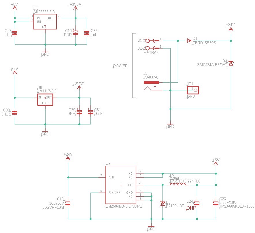
I am bringing up a new board using the LM2594MX-5.0/NOPB using recommended component values per Webench Power Designer. 

This is based on 20VDC-30VDC input range with 24VDC being nominal.  Design is based on 500mA max on-demand current with 150mA typical.  I can provide a BOM if needed.

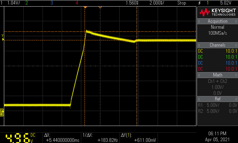
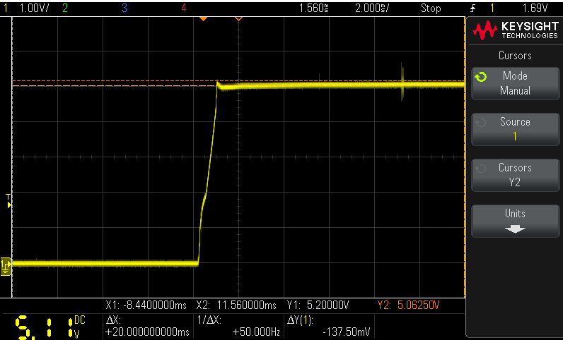
The regulator output voltage consistently overshoots on power up.  This event peaks at close to 10V and stays above 5V for over 3mS. I believe this may be damaging a downstream LDO regulator with a 6V max input voltage.

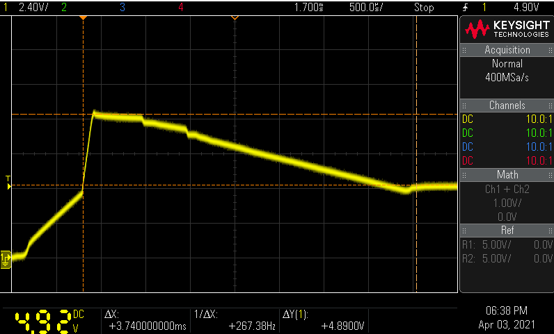
Lower Y cursor represents nominal 5VDC output, upper Y cursor is the 9.89V event peak, span of the two X cursors represents the initial rise above 5V to voltage stabilization)

I have only observed this on power-up and the voltage is steady at 5V +-50mV afterwards. This has happened consistently across 3 PCB assemblies

I've used variations of this same basic design in several products with great success and this is the first time I've seen this. 

A zener diode at the output is effective at clamping the voltage however I'd prefer address the root cause if possible.

Has anyone else resolved a similar issue?  Any suggestions or thoughts are appreciated.

Best Regards,

JLP

  • JLP,

    Please share the board file schematic and layout and I'll take a look.

    You mentioned you've had success in the past. What part of the circuit has changed?

    -Sam

  • Hi Sam,

    Thank you for responding. 

    The LM2594 provides a step-down to feed two linear regulators.

    Screen captures of the relevant parts:

    The PCB is a typical 4-layer stackup: signal-gnd-power-signal.  Looking from the top, the colors are cyan, gray, and blue respectively.  There is no bottom layer visible here.

    links to passive component data sheets in LM2594 circuit:

    input cap: 50SVPF10M

    output cap: TPSA685K010R1800

    diode: B2100-13-F

    inductor: MSS1048-224KLC

    Changes from previous designs:

    -Tantalum vs electrolytic for the output capacitor.  Substituting an electrolytic within the recommended parameters produces similar results however.

    -The diode has changed.  Again, substituting with a familiar part made no difference.

    -The biggest change is that previous designs used the ON Semiconductor adjustable version of the LM2594. I had expected equivalent performance so up to this point have been more likely to suspect the passives.

    JLP


  • JLP,

    It looks like WEBENCH's recommendations are not aligning with the datasheet for this condition (I'll look into this). From the datasheet, we recommend CIN/COUT more like 68uF and 100/200uF. Curious, did your previous designs use these same reduced capacitor values?

    -Sam

  • Sam,

    No, the previous designs were more in-line with your suggestions (47uF / 120uF).  Other than this issue, the current values have so far provided good performance.  WEBENCH is also giving similar results for the LM2596 so I didn't question the discrepancies vs. the data sheet assuming (dangerously) that there were some recent optimizations.

    I'll drop in larger caps to see if that helps resolve the current issue.

    Will keep you posted.

    -JLP

  • Sam,

    With a 47uF input capacitor & 220uF output capacitor, the overshoot is greatly reduced to around 5.6V peak.

    A larger input cap didn't seem to make much difference.  A smaller output capacitor (150uF) increased the peak to around 6V.

  • JLP,

    Yes I will check with the WEBENCH team to fix these suggestions. Thanks for pointing out this issue on LM2596 as well.

    Looks much better! Is there a particular spec you're trying to hit?

    -Sam

  • Sam,

    It is much improved.

    One of the regulators that this feeds has a top operating voltage of 5.5V with 6V absolute max.  I'd like to have some margin below 5.5V. 

    Questions:

    Is this a typical for this device and if so, how much can I expect to diminish this behavior?

    Does the adjustable version have a different startup behavior than the fixed?

    For reference, this is the startup behavior of the older design using an adjustable LM2594:

    Thank you for your help.

    JLP

  • JLP,

    This is an old part. Our newer devices have better soft start so I'd recommend switching to a newer device like the LMR33630 where this should not be a problem if you have a downstream device which cannot handle some overshoot.

    -Sam