This thread has been locked.

If you have a related question, please click the "Ask a related question" button in the top right corner. The newly created question will be automatically linked to this question.

TPS23754: Power management forum

Part Number: TPS23754

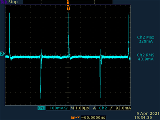
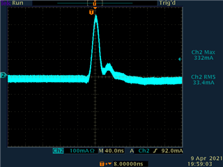
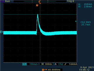
I used TPS23754 to design a 48V to 12V POE power DC-DC converter.

( Schematic is attached " named POE.pdf )

Recently, I changed the Mosfet Q2 to a other 2nd source component.

I found R241 should be changed from 4.99K to 0 ohm, or this design with this 2nd source component have damage problem.

I also found other TI reference design ( refer to slvu301.pdf )  have a similar design that the base of Q3 also doesn't connected any series resistor to limit the base current.

Is it safe to use 0 ohm for R241 in my design ?

POE Circuit.pdfslvu301.pdf

  • Hello Arron, 

    As you pointed out, lowing R241 increases the current through the BJT. The purpose of the BJT is to pull the Gate down of Q2. My guess is your second source has a higher gate charge than your first source. The only concern for you is the BJT size, it looks okay. 
    In truth, we do not recommend a 12V sync flyback at all because they typically have design issues like this, and the efficiency boost is 1% at best. 

    I would recommend a diode flyback for 12V. 

    If this post answers your question, please indicate so by marking this thread as resolved. Thank you.


    Regards, 


    Michael P.

    Applications Engineer

    Texas Instruments 

  • Hi Michael :

    I attached the datasheet of MMBT3906 for your reference.

    Q1) Do you mean the current BJT I used is okay with R241 of 0ohm ?

    Q2) Is there any document or information available for me to learn the relation between BJT size and series resistor connected to the base of BJT ?

    Thanks

    Arron

  • MMBT3906.pdfHi Michael :

    I attached the datasheet of MMBT3906 for your reference.

    Q1) Do you mean the current BJT I used is okay with R241 of 0ohm ?

    Q2) Is there any document or information available for me to learn the relation between BJT size and series resistor connected to the base of BJT ?

    Thanks

    Arron 

  • Hello, 

    1.) Yes

    2.) No, but the BJT size is good. 

    If this post answers your question, please indicate so by marking this thread as resolved. Thank you.


    Regards, 


    Michael P.

    Applications Engineer

    Texas Instruments 

  • Hi Michael :

    I measured the base current of Q1 ( refer to the circuit in POE Circuit.pdf ) with 0 ohm R241.

    The peak current is around 330mA and duration time is around 20ns.

    Q1) How can I know it's ok or not  ( the case temperature of Q1 is around 95 degrees in my system )?

    I also found the peak current could be reduced to around  238mA ( duration time is less than 20ns ) if I removed U46 and C395.

    Q2) Can I remove U46 & C395 in my design to lower the base current of Q1 with 0 ohm R241 ?

    A)current with R241 = 0ohm and populated the U46 & C395

    B)Current with R241 = 0ohm and remove U46 & C395

    Thanks 

    Arron

  • Arron, 

    1. Is the rated current higher than the peak current? Does it meet your thermal spec. 

    2. That would match the design, but remember the design is a 5V design not 12V. 

    If this post answers your question, please indicate so by marking this thread as resolved. Thank you.


    Regards, 


    Michael P.

    Applications Engineer

    Texas Instruments