This thread has been locked.

If you have a related question, please click the "Ask a related question" button in the top right corner. The newly created question will be automatically linked to this question.

UCC28780: UCC28780 EXCEL Design calculator

Genius 9880 points
Part Number: UCC28780

Hi Team,

Customer is getting negative value for resistor and they want to know how to change it. Below is the inquiry.

"Hi, I am on the way to design a ACF Flyback converter with the Ti  UCC28780 chip. Therefore I use the EXCEL Design calculator tool, but with my input values (Vin= 25-40V/DC) Vout =5V, P=5W, fsw=100kHz and asHigh and Low side switch I use Mosfet IRFR120ZPbF. The problem now is that I get a negative value for the bleeding resistor. Wha do I have to change?

UCC28780 (1).xlsx

"

Regards,

Maynard

  • Hi Maynard,

    I found that you set the brown in voltage at 12V , but UCC28780 needs around 20V input to start switching.

    I think that UCC28780 is not suitable for your application.

    if the input spec is 25~40Vdc(even at brown in voltage) , you can refer the reference design as below.

    https://www.ti.com/tool/PMP9009

  • Hi Adam,

    Below is the response of the customer.

    "

    Thank you for your fast and good answer.

    The  UCC28700DBV won't fit to my problem, because I need an Active Clamp Flyback controller.

    Is there one which fits to my specifications?

    I additionally can add a 24V auxiliary winding, if this would help, but the excel calculator seems not to change the bleeding resistor problem.

    "

    Regards,

    Maynard

  • Hi Maynard,

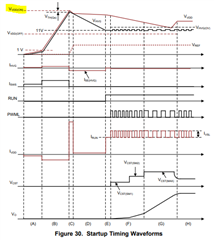
    you can refer datasheet figure 30 , Vdd must increased up to Vdd(on) threshold then start switching, the Vdd(on) threshold is 17.5V(typ) , so even you set auxwinding turn ratio to 24V , the PWM is not switching so auxwinding can't provide the voltage to Vdd pin.

  • Hi Adam, 

    Customer have provided the following responses.

    1. I don't understand why it should not be possible to have a auxiliary winding with 24V and enable the threshold value of the VDDon. All schematics and application notes are powering the VDD pin by the Auxiliary winding. Additionally I am sorry, because I set the Brown In INvoltage to 12V but it is 25V (Vinmin) in the EXCEL calculator. So the Bleeding resistor problem is fixed but now I have a negative value for Csws.

    2. Customer provided a new excel file and they want to know if this will work.

    UCC28780_recheck_.xlsx

    Customer have a 24V auxiliary winding for supply and they want to have an active clamp flyback from 25-40 Vin and 5V Vout and 5W Pout.

    Regards,

    Maynard

  • Hi Maynard,

    sorry for late , I just take personal leave this week and back to office today.

    1. the 24V auxiliary winding is based on the turn ratio with output voltage at steady state,  during the startup, PWM is not switching to provide the power to secondary , the output voltage can't be up to 5V , and Auxwinding can't get any voltage too. you can share the datasheet section 7.4.8 Startup Sequence to your  customer.

    2. the currently Auxwinding voltage is set to around 14V (5*100/36)based on the excel , if they want to change to 24V setting , the Auxwinding should increase up to 173 turn , and RVs1 & RVs2 also need to be changed.

    Adam

  • Hi Adam,

    Thank you for your response. Below has follow up question.

    " " the currently Auxwinding voltage is set to around 14V (5*100/36)based on the excel , if they want to change to 24V setting , the Auxwinding should increase up to 173 turn , and RVs1 & RVs2 also need to be changed." If I change this, is then the converter working with a 5V output voltage and a 12V Auxiliary winding? Because for the start up the High voltage sensing circuit in combination with the SWS node is used?

    One more question, what should the Input Voltage for Burst Mode Setting be? What is meant by high lane in this case?"

    Thank you.

    Regards,

    Maynard

  • Hi Adam,

    Any update on this?

    Thankyou

    Regards,

    Maynard

  • Hi Maynard,

    if you change the Auxwinding up to 173 turn , the Vdd is around 24V Auxwinding voltage during 5V output, it is based on your customer previous requirement.

    the high line setting means the highest normal input voltage , for example , the universal input is 90~264Vac , and we may set the burst mode at 230Vac.