This thread has been locked.

If you have a related question, please click the "Ask a related question" button in the top right corner. The newly created question will be automatically linked to this question.

TLV62585: Output higher than the expected

Part Number: TLV62585

Hi.

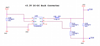
I am using the TLV62585DRL, the output voltage expected is 3.3V, but I am having in some boards 3.5-3.6V or even the voltage change from 3.35 to more than 3.6 if the input voltage change. The input voltage range is 3.4 to 4.2V

Attached is the schematic image.

Please, if you can help me, would be great.

  • Hi User,

    Thanks for your question.

    Could you provide more data on the problem? For example:

    - Do you have this problem only for low output current (some mA) or also for high currents (1-2A)?

    - Is the DC value of the output shifted (for example to 3.6V), or is this only an AC behavior due to transitions (for example a step on VIN)?

    - When VOUT is different from the nominal value, is also the FB voltage different than 0.6V?

    - If you could provide us the waveforms of VIN, VOUT, FB and SW when you detect this problem it would be very helpful.

    Please send us also the layout for review.

    Thanks,

    Stefano

    All information in this correspondence and in any related correspondence is provided “as is” and “with all faults”, and is subject to TI’s Important Notice (http://www.ti.com/corp/docs/legal/important-notice.shtml).

  • Hi. 

    We did more testing and we resolve that problem, but I have a similar problem. In two of the boards I would want a different output voltage, 3.0V instead 3.3V, so, I changed one of the feedback resistors, but I didn't get the 3.0 V, I have lower voltages or some times variables voltages from 1 to 3 V, after that, I placed again the original resistor but same problem, I didn't measure 3.3V, could you tell me why if I only change one of the feedback resistors I have a lower voltage or a variable voltage even if I placed again the original resistors?

    The feedback voltage in two of the converters is 0.6 V , in one is 1.2 V and in other is variable even reaching 3.3 V. 

    Something that I noticed is the impedance in the 3.3V voltage rail, in the boards that are working well I have more than 400 KOhms, but in the boards with a lower voltage or variable voltage I measured less than 400 KOhms, commonly between 150 KOhms and 380 KOhms.

    Thanks

  • Hi Asael,

    Thanks again for your question.

    From your description it seems to me that you have a problem of setup (maybe the connection of the feedback resistors is not always optimal).

    In particular, the FB value should be 0.6V regardless of the VOUT setting.

    Can you please confirm that when the FB voltage is 0.6V also the VOUT is set to the correct value?

    I would advise you, whenever you don´t have a 0.6V on the FB, to do some tests to assure that the setup is properly working (resolder the feedback resistors to check connections, try to change PCB or IC to check if the board/device has been damaged, ...).

    Please ask again if you need further support. 

    Thanks,

    Stefano

    All information in this correspondence and in any related correspondence is provided “as is” and “with all faults”, and is subject to TI’s Important Notice (http://www.ti.com/corp/docs/legal/important-notice.shtml).

  • Hi Stefano.

    Thanks for the reply. I am waiting for some components to change them in the boards because I tried to resolder the components but I had same results. When I have the new components and place them, in a couple of days, I will give you an update. 

    Regards.

  • Hi Asael,

    Thanks for your update.

    Let me know if I can do anything else to support you.

    Thanks,

    Stefano

    All information in this correspondence and in any related correspondence is provided “as is” and “with all faults”, and is subject to TI’s Important Notice (http://www.ti.com/corp/docs/legal/important-notice.shtml).