This thread has been locked.

If you have a related question, please click the "Ask a related question" button in the top right corner. The newly created question will be automatically linked to this question.

BQ24250: Charging circuit not working.

Part Number: BQ24250

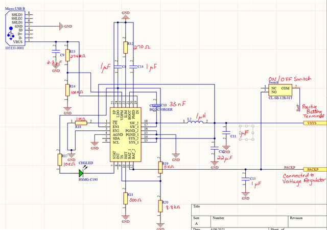
I have soldered on the following charging circuit onto a printed circuit board. I followed the datasheet and determined that these were the proper components. I asked in an earlier question concerning how to configure En1, En2, SDA, and SCL on this forum, and based on the response this is how I arranged it. When I plug in the micro usb type b, the battery won't charge. I get an input voltage of 5 volts. The battery is a 3.7 V 290 mAh battery. Is there any component value off, or any issue with my design that may cause the charger to not work? I am only using it as a stand alone charger. 

  • Hi Tara,

    What do you mean by the BAT is "connected to a voltage regulator"? Can that regulator sink current? If not, the regulator may be hitting 4.2V and the charger is terminating.

    Also, if TS is not connected to a thermistor, TS function should be disabled pulling TS pin high to LDO pin.  If you remove R20, does the converter start charging?

    Regards,

    Jeff 

  • To clarify about the voltage regulator, I mean that the battery is just also connected to the voltage regulator circuit (with buck boost converter TPS63020QDSJTQ1).

    After removing R20, should I connect TS to ground?

  • Hi Tara,

    Usually another buck converter would be connected to the SYS pin not BAT.  If connected to BAT, the charger is not able to distinguish between charging current and current going to the TPS device and so the charger may never terminate charge.  Regarding pulling TS to ground, no.  Pull TS to LDO in order to disable the TS function.

    Regards,

    Jeff