This thread has been locked.

If you have a related question, please click the "Ask a related question" button in the top right corner. The newly created question will be automatically linked to this question.

TL5001A: TL5001A compensation network

Part Number: TL5001A
Other Parts Discussed in Thread: TL5001,

Hello,

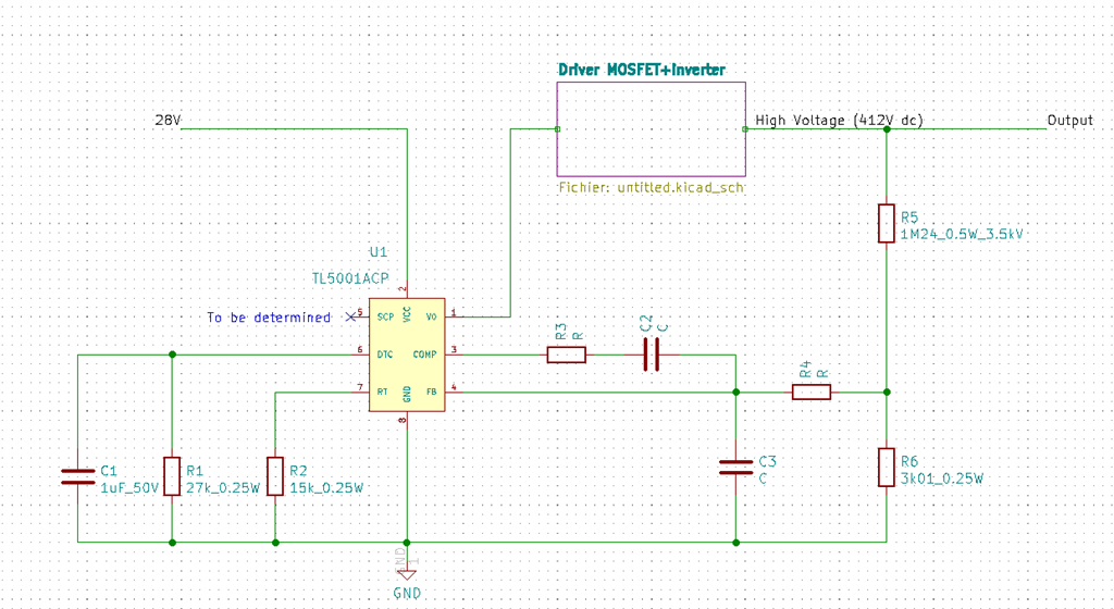
I'm trying to use a TL5001 with a transformer in loop. Sometimes ti runs as expected, sometimes not. I'm pretty sure that my issue comes from compensation network but I'm unable to find a solution.

My design:

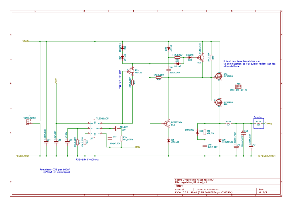
V20 is a 28V power supply (no regulation, it directly comes from a 230V/20Vac transformer followed by a rectifier network, a lot of condensators (38 * EKY-500ELL272MM40S) with of course a preload and discharge circuit. For my tests, as TL5001A is not stable, I have removed C35.

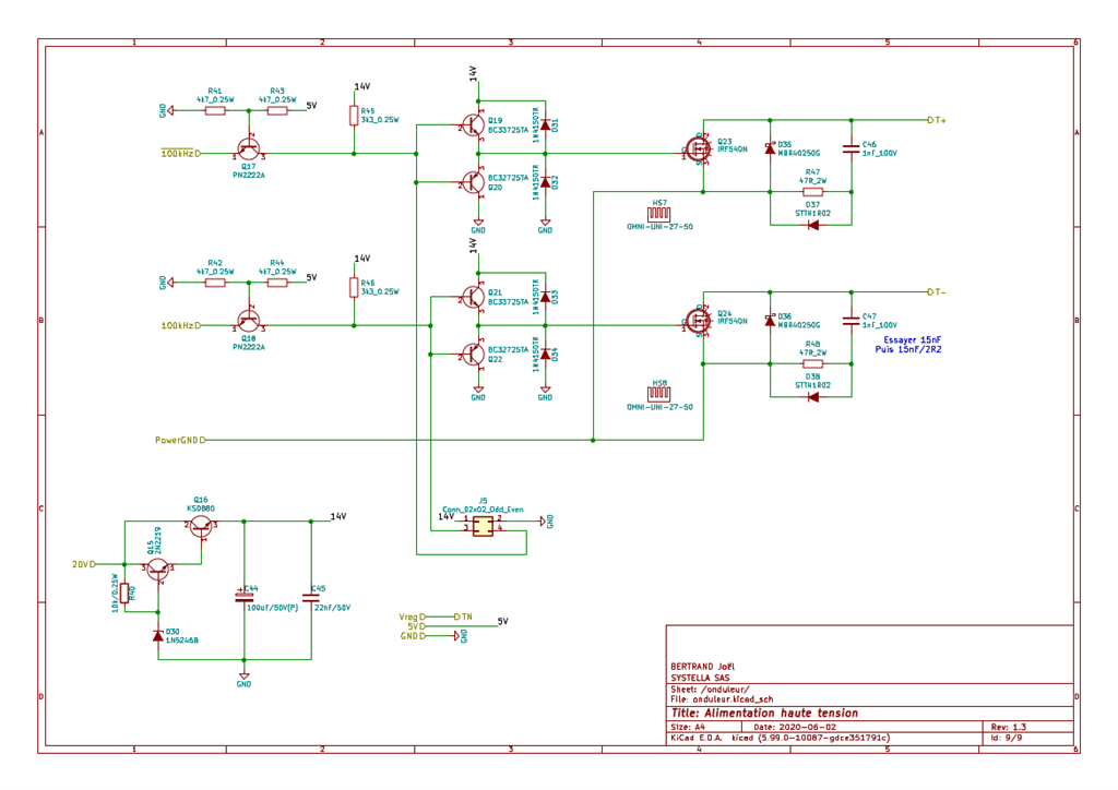
This circuit generates two commands for gates of a push-pull inverter (@ 100 kHz). 100 kHz signal is generated by a crystal.

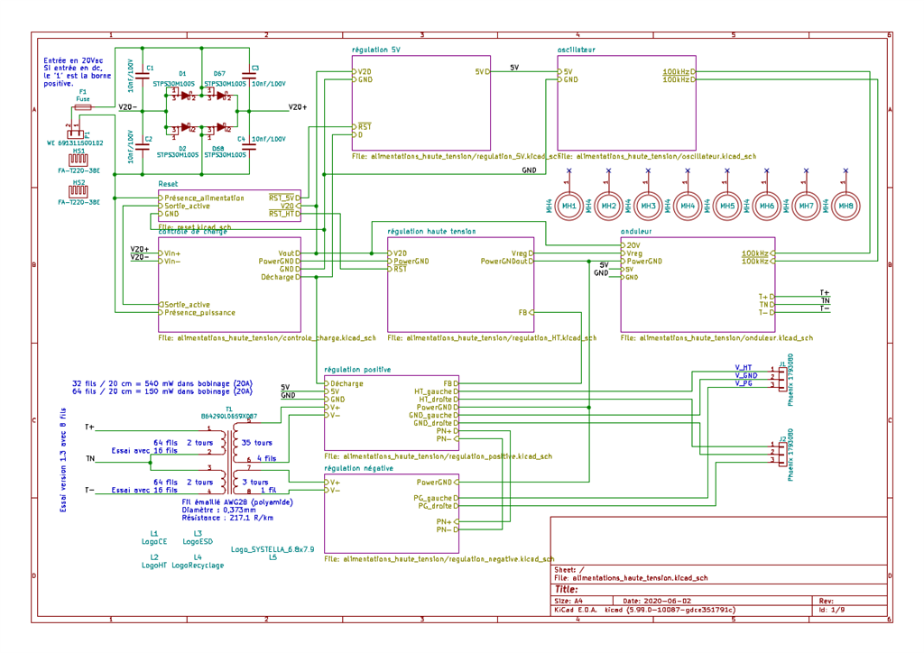
T+, TN and T- are directly connected to a transformer.

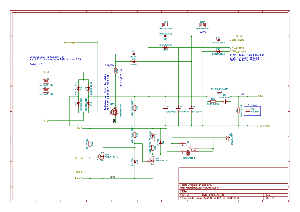
Output of this transformer is rectified and filtered. Feedback is taken after this filter.

Components marked "deleted" are removed from PCB. Converter starts but can enter in a unstable state : it starts, stops and quickly restarts. I know that transformer is a low pass filter, but its bandwith is greater than 100 kHz and main regulator works at 400 kHz. How can I solve this compensation network ?

Best regards,

JB

  • To stabilize circuit, datasheet indicates that it is possible to use a gain < 1. I suppose this gain is set by R34 (other values are fixed). I have reduce R34 until 33R without notable modifications.

    I think I only have two solutions:

    - reduce gain (with R34)

    - add a low pass filter (to only have gain at very low frequencies)

    Is the following circuit sufficient to avoid oscillations? I understand that high pass filters in datasheets compensate phase shift given by LC filter. But in my case, I don't have a second order filter... Comment are welcome.

  • Hi Joel,

    Thank you for post.  The TL5001 is an old device and you may consider some newer devices in your design, which may have better support tools like Webench, Pspice, and design calculators.

    Anyway, this device is based on voltage mode control, so naturally it requires type-III compensation, namely and RC in parallel with R5 and removal of C3 in above circuit. To stabilize the loop you can reduce R3 to zero and add a large capacitor at C2.  Can you try 100nF first?

    Best Regards,

    Youhao Xi, Applications Engineering

  • Hello,

    Thanks a lot for your answer.

    If you have another controller in DIP package with the same functionalities, I could change. I don't believe it's the case and I'm pretty sure I will have same trouble with another similar controller. I don't understand why TI doesn't provide Spice model as PSpice contains a model for this basic component.

    That being said, I have done some measurements and I'm sure that TL5001 is not stable as gain in feedback path is greater than 1 in high frequencies (where phase shift in open loop is greater than 90°, don't forget I have a order 4 or 5 low pass filter instead of regular LC filter in open loop). If I add RC in parallel with R5, I will increase this gain in HF. My first idea was to reduce this gain with a low pass filter to avoid phase trouble. But I will try to remove R3 to check result.

    Best regards,

    JB

  • I have tested with R3=0 and C2=100n. Same result. I will try with a low pass filter.

  • Hi Joel,

    Could you share some key waveforms to show the issue?  Also, please let me know the results with your low pass filter. 

    Thanks,

    Youhao

  • Hi Youhao,

    Low pass filter is not an option, I have tried without any success. Gain of error amplifier is too high to stabilize system.

    I will try to post some chronograms, but in a couple of days. I have to change IRF540N by some mosfets that support higher voltage. Yesterday, oscillations have destroyed one of these transistors.

    Best regards,

    JB

  • Hi Joel,

    Please share some key waveforms so we may get more insight to the problem. 

    Thanks,

    Youhao