This thread has been locked.

If you have a related question, please click the "Ask a related question" button in the top right corner. The newly created question will be automatically linked to this question.

BQ33100EVM-001: EVM configuration guidance sought

Part Number: BQ33100EVM-001
Other Parts Discussed in Thread: BQ33100, , EV2400, BQSTUDIO

Hi,

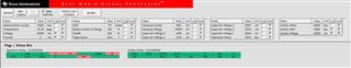
I'm using the BQ33100EVM-001 and EV2400. I have just flashed the BQ33100 firmware to the latest version. Device is shown as bq33100 R0, FW version V0_15_BLD0017

I have 5x 100F, 2.7V, 15mOhm super capacitors wired to the EVM.

My EVM is connected to a 14V PSU.

The board is running but i wanted clarification on some of the settings.

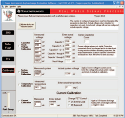
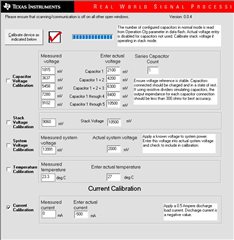
I've carried out a Capacitor Voltage Calibration, with the voltage increasing by 2.1V (2100mV, 4200mV, 6300mV, 8400mV and 10500mV.

  1. On the System Voltage Calibration the measured system voltage is shown as 13991mV but the actual system voltage is shown as 2000mV. I don't appear to be able to change this, such that its saved. it always reverts back to 2000mV.
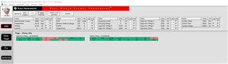
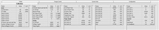
  2. In SBS the capacitance is reported as 2.0F and ESR 400mohm.
  3. In Dataflash>System Data the Design Capacitance, Init 1st Capacitance and Capacitance are all 2.0F. How do i change these to reflect the capacitance used? What is the difference in the three items?
  4. In Dataflash>System Data the Design ESR, Initial ESR and ESR are all 400mohm. How do i change these to reflect the ESR of the capacitors used? What is the difference in the three items?
  5. In Dataflash>System Data the Design voltage is 9000mV. What is this value referring to?
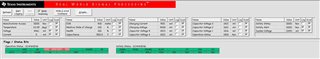
  6. In SVS in the safety status i see a OV flag set. Why?

Thanks.

  • Hello Howard,

    Is this still happening after the calibration? Can you share a screenshot of your bqStudio dashboard?

    You will need to let the gauge learn the ESR by performing a learning cycle on the capacitors.

    Can you share your .gg file with the configurations?

    Sincerely,

    Wyatt Keller

  • Hello Wyatt,

    I still have the same issues, though its probably down to a lot of confusion on my part.

    Currently, the Operation status is showing -

    From this i believe a Capacitance learning is in progress, started by me issuing a 24(hex) command followed by 25(hex) command in the Pro section. However, this has been like this for in excess of 1hour. I note the individual capacitor voltages are dropping, yet the fuel gauge still shows 100%.

    My set up is still the same. 14V supply to the EVM. Five 100F, 2.7V caps are attached to the EVM. I have done a Capacitor Voltage Calibration.

    I also attach the Data Flash export file in the hope you can spot the issues and point me in the right direction to get this going properly.

    i had hoped to set the board so the total stack voltage was 12.5V, limiting each capacitor to 2.5V. Id be grateful if you could give me a basic step by step guide as to what values i should be changing and what commands i need to issue to do this?

    export.txt
    [Header]
    bq EVSW Version = 0.9.92	
    DeviceName = bq33100 v0.15
    Time = 12/04/2021 16:06:24	
    
    
    [Voltage(Safety)]
    OV Threshold = 100
    OV Recovery = 0
    OV Time = 2
    CIM Fail Voltage = 550
    CIM Time = 10
    CIM Recovery = 500
    Min CIM Check Voltage = 1000
    [Current(Safety)]
    OC Chg = 1000
    OC Chg Time = 5
    OC Chg Recovery = 900
    CLBAD Current = 15
    CLBAD Time = 60
    CLBAD Recovery = 10
    Current Recovery Time = 5
    OC Dsg = 0F
    OC Dsg Time = 0F
    OC Dsg Recovery = 5
    SC Chg Cfg = F4
    SC Dsg Cfg = F7
    SC Recovery = 1
    [Temperature(Safety)]
    OT Chg = 68.0
    OT Chg Time = 2
    OT Chg Recovery = 63.0
    [AFE Verification(Safety)]
    AFE Fail Limit = 100
    AFE Init Retry Limit = 6
    AFE Init Limit = 20
    
    [Charge Cfg(Charge Control)]
    Chg Voltage = 10000
    Chg Current = 500
    Chg Enable Delay = 0
    [Full Charge Cfg(Charge Control)]
    Taper Current = 3
    Taper Voltage = 200
    Current Taper Window = 2
    FC Set % = -1
    FC Clear % = 98
    [Capacitance Balancing Cfg(Charge Control)]
    CB Threshold = 800
    CB Min = 5
    CB Restart = 10
    
    [Data(System Data)]
    Design Voltage = 9000
    Manuf Date = 01-Jan-1980
    Ser. Num. = 0001
    Design Capacitance = 500.0
    Init 1st Capacitance = 100.0
    Capacitance = 500.0
    Design ESR = 400
    Initial ESR = 400
    ESR = 400
    Manuf Name = Texas Inst.
    Device Name = bq33100
    Init Safety Status = 0000
    [Manufacturer Data(System Data)]
    Pack Lot Code = 0000
    PCB Lot Code = 0000
    Firmware Version = 0000
    Hardware Revision = 0000
    [Manufacturer Info(System Data)]
    Manuf. Info = 0123456789ABCDEF0123456789ABCDE
    [Lifetime Data(System Data)]
    Lifetime Max Temp = 57.4
    Lifetime Min Temp = 22.2
    Lifetime Max Capacitor Voltage = 2434
    
    [Registers(Configuration)]
    Operation Cfg = 0448
    FET Action = 0000
    Fault = 0000
    [AFE(Configuration)]
    AFE State_CTL = 00
    [Power(Configuration)]
    Flash Update OK Voltage = 4000
    Shutdown Voltage = 4000
    
    [System Requirement(Monitoring)]
    Min Power = 10
    Required Time = 60
    Min Voltage = 4000
    [Charging Voltage(Monitoring)]
    V Chg Nominal = 9000
    V Chg A = 9500
    V Chg B = 10000
    V Chg Max = 10500
    V Learn Max = 10500
    [Learning Configuration(Monitoring)]
    Learning Frequency = 2
    Measurement Margin % = 1
    Max Chg Time = 300
    Max Dsg Time = 10
    Learn Delta Voltage = 500
    Cap Start Time = 320
    [Current Thresholds(Monitoring)]
    Dsg Current Threshold = 10
    Chg Current Threshold = 0
    
    [Data(Calibration)]
    Current Gain = 20
    CC Delta = 20
    Cap1 K-factor = 7700
    Cap2 K-factor = 20500
    Cap3 K-factor = 20500
    Cap4 K-factor = 20500
    Cap5 K-factor = 20500
    K-factor cap override flag = 9669
    System Voltage K-factor = 24500
    Stack Voltage K-factor = 24500
    K-factor stack override flag = 0000
    CC Offset = -1.14
    Board Offset = 0
    Int Temp Offset = 0.0
    Ext1 Temp Offset = 0.0
    Ext2 Temp Offset = 0.0
    ESR Offset = 0
    [Config(Calibration)]
    CC Current = 3000
    Voltage Signal = 10500
    Temp Signal = 298.0
    CC Offset Time = 250
    ADC Offset Time = 32
    CC Gain Time = 250
    Voltage Time = 2080
    Temperature Time = 32
    Cal Mode Timeout = 300
    [Temp Model(Calibration)]
    Ext Coef a1 = -14812
    Ext Coef a2 = 24729
    Ext Coef a3 = -21265
    Ext Coef a4 = 28353
    Ext Coef a5 = 759
    Ext Coef b1 = -399
    Ext Coef b2 = 764
    Ext Coef b3 = -3535
    Ext Coef b4 = 5059
    Ext rc0 = 11703
    Ext adc0 = 11813
    Rpad = 87
    Rint = 17740
    Int Coef 1 = 0
    Int Coef 2 = 0
    Int Coef 3 = -12263
    Int Coef 4 = 6106
    Int Min AD = 0
    Int Max Temp = 610.6
    [Current(Calibration)]
    Filter = 239
    Dead Band = 5
    CC Deadband = 2.9
    

    Thanks

    Howard

  • Hi Howard,

    Can you share a screenshot of Calibrate section?

    Design Voltage, Design Capacitance and Design ESR values are the design values of the capacitors used, you have to change those to the actual values. Initial values are the first learned values. Please refer to the datasheet for more information.

    For learning, you also need to connect a load to CAPOUT and VSS, for learning process, please refer to datasheet 8.3.1 section.

    Application report SLUA751 could be useful.

    Best Regards,
    Abraham

  • Hi Abraham,

    Could you tell me exactly what values to change and to what? I'm going around in circles reading the datasheet and all the associated documents and making no headway. Yesterday, it was stuck in the learning mode for hours and then quite a number of the components on the eval board started to get ridiculously hot.

    My five Capacitors are (each) 100F, 2.7V and 15mOhm and i want to limit the voltage on each capacitor to 2.5V. I want to be able to balance the voltage across the Capacitors.

    I presume by Calibrate section you want the Calibration tab under Data Flash? Wasn't that information available in the data i posted earlier?

    Howard

  • Hi Howard,

    Set cell number to five,DF:Configuration:Registers:Operation Cfg:CC2, CC1, CC0 = 100, STACK=0

    Set DF:Charge Control:Charge Cfg:Chg Voltage, DF:System Data:Data:Design Voltage, and DF:Monitoring:Charging Voltage:V Chg Nominal to 2.1 V (use recommended value by the supercapacitor manufacturer for achieving the lifetime ) × 5.

    Set DF:Monitoring:Charging Voltage:V Chg Max and DF:Monitoring:Charging Voltage:V Learn Max to 2.5V x 5.  Set DF:Monitoring:Charging Voltage:V Chg A and DF:Monitoring:Charging Voltage:V Chg B to lie equally between V Chg Nominal and V Chg Max. 

    Set DF:System Data:Data:Design Capacitance = 20 F
    DF:System Data:Data:Init 1st Capacitance = 20 F
    DF:System Data:Data:Capacitance = 20 F

    Set DF:System Data:Data:Design ESR = 75 mΩ
    DF:System Data:Data:Initial ESR = 75 mΩ
    DF:System Data:Data:ESR = 75 mΩ

    By Calibrate section I meant something like this

  • Hello Abraham,

    Thanks for that, i will try it later.

    Its strange; i fired the board up first thing and it went to Cell Balance, resulting in the following window -

    Which is the first time i havent had an OV flag.

    Here is the Calibrate window -

    I'll post later when ive followed your steps.

    Howard

  • Hi Howard,

    On the System Voltage Calibration the measured system voltage is shown as 13991mV but the actual system voltage is shown as 2000mV. I don't appear to be able to change this, such that its saved. it always reverts back to 2000mV.

    For this question, check the box in front of System Voltage Calibration, then change the actual system voltage to the measured system voltage, then calibrate the device.

  • Hello Abraham,

    I seem to be making progress, thanks to your help.

    SBS screen is now showing correct ESR and Capacitance -


    Why is the Cap1 K-factor so out of step with the others-

    Its been hit and miss trying to do a capacitor learn as it normally results in a LCTO. Am i correct to increase the Max Chg Time to increase the timeout?

    Is there a way i can read the status of CHGLVL1 and CHGLVL0 pins?

    Thanks

    Howard

  • Hi Howard,

    Cap K-factor is the ADC voltage translation factor, it is not used by default.

    Yes you can increase the Max Chg Time.

    CHGLVL1 and CHGLVL0 are output pins, you can read the ChargingVoltage() and use the table below to determine the state of the pins if the gauge is in discrete charge mode.

  • Hi Abraham,

    I see in the charge control (8.3.3) reference is made to discrete and smart control. How do i know if im using discrete or smart control?

    8.3.1.1 seems to indicate that the BQ33100 can change the charging voltage at step 6? Is this smart control?

    If i change the charge voltage using commands 32-35 is this discrete control?

    Can i configure the BQ33100 to only manage charge and cell balancing and not do any learn? (I would preload the cap and esr values)

    Can you provide instruction on how to make a read of the DF to obtain System Data: Design Capacitance?

    What commands do i need to send to set the learn frequency to 10mins - i know from 8.3.1.2 i send a value of 250 but how?

    Thanks for your continued support

    Howard

  • Hi Howard,

    You can change the learning frequency in Data Flash: Monitoring: Learning Configuration: Learning Frequency in the software, change the value and click Write All. 

  • Hi Abraham,

    What about my question on discrete and smartc control?

    How do i change the dataflash from a microcontroller? What is the command sequence?

    Howard