


Other Parts Discussed in Thread: TIDA-050045
Hello,
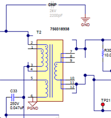
your reference schematic looks like a alpha version. The transformer T2 is for example not really connected:
Also the diode D24 should make the connection between VSS and PGND, but the diode is not mounted...
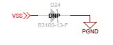
And I can't find any other connection between VSS and PGND. How should it works? Or should the Diode D24 replaced by a 0R Resistor / short circuit?
In the reference Design from TPS23730EVM-093 it looks not much better. The diode D24 is there also not mounted. In the Layout guidelines is written:
Place the Schotty diode between VSS and RTN as close to the IC as possible, preferably on directly on the
opposite side of the board (ex. The TPS23730EVM-093 places the IC on the top side, so the diode is on the
bottom side directly underneath it).
(RTN is connected to PGND)
In the reference Layout is on this position is only a Diode D23:
Top side 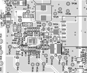 Bottom side
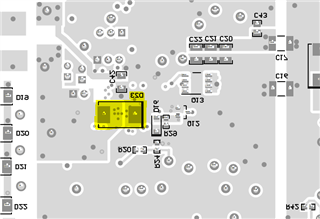
Could it be, that you have here not published the final versions?
Best regards - Christian Heidbreder
