This thread has been locked.

If you have a related question, please click the "Ask a related question" button in the top right corner. The newly created question will be automatically linked to this question.

LM25085: Startup simulation overshoot

Part Number: LM25085

Hello,

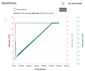
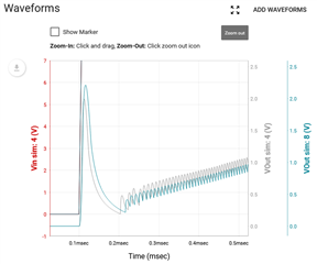
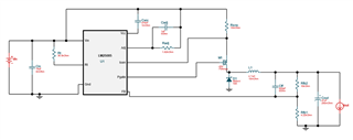
I'm trying to design a 4.2V regulator using the LM25085.  I have run a few webench-design based "startup" simulations and, in each case, the simulation shows a significant output voltage overshoot at the very beginning of startup.  The absolute max input voltage for my application is 4.8V.  As you can see from the screenshots below, the overshoot in each of my simulations exceeds 5V.  Is this overshoot "real" or just a product of simulation?  If it is real, is there a way to reduce the overshoot so that I can be guaranteed it would never exceed my 4.8V absolute max input voltage spec?

"Zoom Out" simulation view

Zoomed in simulation view

Simulated Webench design

Thanks in advance,
Paul W.

  • Paul,

    That overshoot is unexpected.

    From the way VOUT rises with VIN rising it would appear VOUT is capacitively coupled to VIN.

    This is likely due to parasitic capacitances of the MOSFET and Diode AC-coupling the VIN transient to the switching node.

    With a more controlled VIN rising this is unlikely to appear. 

    Also that VOUT transient rises to 2V, not 5V as you mention. The VOUT axis is separate from the VIN axis.

    It is still good to understand this and get it under control.

    Also an RC snubber on the switching node would help control slew rate and reduce the capacitive coupling effect. This RC snubber would be parallel to D1.

    Let me know if you have further questions.

    -Orlando

  • Orlando,

    I had been looking at the right-side y-axis for Vout on all of the other simulations.  How embarrassing that I misinterpreted it in this plot.  I see now that the spike is just over 2 volts.

    And yes, it's still good to understand the source and remedy.

    Thanks very much for your help!

    Paul