This thread has been locked.

If you have a related question, please click the "Ask a related question" button in the top right corner. The newly created question will be automatically linked to this question.

TPS54560: Capacitor at FB pin (TPS54560)

Part Number: TPS54560

Hi,

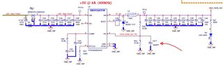
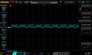
We have used two of this part in one of our PCBs. We used the typical application circuit and we followed all guides in the datasheet as well. We added a 1nF capacitor between the FB pin and ground to have less noise at the output. Amount of load current is small and around 50mA. I am measuring around 100mV ripple with frequency of 12kHz at the output. When I remove the capacitor at the FB pin, the ripple is reduced to nearly half and its frequency is increased to double. We don't have this frequency in our design. Even in no-load condition, we have similar ripples (100mV) at the output.

One of the TI colleague sent me a spreadsheet to do design calculations. I used it to calculate the design value. We have relatively similar values in our design. The problem that I have seen is about adding a capacitor to FB pin. As I mentioned, I am measuring different ripple levels at the output with and without this capacitor. I have checked 2 separate PCBs and they have similar responses.

There isn't any information about capacitance at the FB pin in the datasheet or in the spreadsheet. Really, we expected to have better response from ripple level point of view with adding a capacitor to the FB pin but it seems the pin is very sensitive to the value of the capacitance at the FB pin.

Any advice in this regard?

  • Hi,

    yes in general we do not recommend a capacitor on the FB node since that could create a pole that may cause instability in your system. The other thing that may cause a noise issue on the FB node is the layout, in general we put the top and bottom feedback resistor close to the IC such that the noise coupling is small. We need to keep the FB trace short to avoid noise coupling. 


    Do you have a schematic for your design? Alternatively you can check the spreadsheet for the component design of your system below or Webench would be another source to double check the component selection

    Normally the output voltage ripple frequency is the same as your switching frequency. 

    5773.TPS54360-361FAMILY_CALC_TOOL_REVE.xls

    Thanks

    -Arief 

  • Hi Arief,

    Thanks for your email. Below is the schematic for our design. I checked the layout and the top and bottom feedback resistors are as close as possible to the IC with the FB trace short. FYI, we have modified the design and we removed the capacitor (C277) from the design.

    Regards,

    Mohsen

  • Hi Mohsen,

    The design looks reasonable, the one concern that i have is the output capacitor may be derated heavily with the 10V rating for a 5V supply. 
    I would say you need roughly 88uF - 100uF output capacitor after derating. Do you have the SW node oscilloscope waveform at 4A load?

    Thanks

    -Arief

  • Hi Arief,

    Below is the scope capture of the SW nose. Really, we designed the circuit to deliver 4A considering the TI chip capability but we don't have that amount of load current. The load current in our circuit is less than 0.5A. The Oscope capture shows the converter works in DCM mode.

    Regards,

    Mohsen

  • Hi Mohsen, 

    The waveform looks ok. As long the waveform looks stable in CCM mode, then i think it should be ok. 

    I was worried that the additional 1nF on the FB node may cause instability on your system and causing irregular switching that causes your output voltage ripple to go up. 

    Thanks

    -Arief

  • Hi Arief,

    Thanks for your email. Based on the scope capture, I think the converter works in DCM in our application not CCM.

    Really, I was looking for a lesson learned from this observation and I realised the FB pin is sensitive to the capacitance value at the Pin node and we need to consider this parameter/limitation at the layout level.

    Thanks for your help.

    Regards,

    Mohsen

  • No problem Mohsen, let us know if you have any additional questions. 
    I will close the thread for now

    Thanks

    -Arief