This thread has been locked.

If you have a related question, please click the "Ask a related question" button in the top right corner. The newly created question will be automatically linked to this question.

LM61495-Q1: LM61495QRPHT-Q1

Part Number: LM61495-Q1
Other Parts Discussed in Thread: LM61495

Hi. Teams

I would like to apply LM61495QRPHT-Q1 to the project.
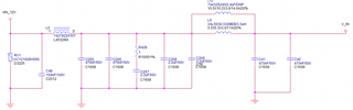
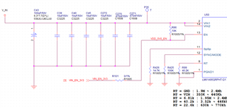
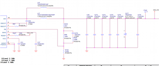
I am trying to configure the circuit as below, but I have some questions.


- INPUT : 12V (Input range : 4V ~ 36V)

- Switching Frequency : 200Khz ~ 2.5Mhz

- OUTPUT : 5V

- Iout : 10A 

1. The input & output L value and size vary depending on the frequency characteristics.

    I need to evaluate it, but i want to compare it to 400Khz and 2.2Mhz, is the circuit below correct?

    If you have any other solutions, please share them with  me.


2. In the figure below, the Iout differs between 400Khz and 2.2Mhz. Does this differ in the same IC?

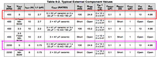
3. If so, 10A operation is possible for 400KHz and 2Mhz, and I request IC that meets the above conditions.

Thanks

  • Hi,

    The two schematics look okay and follow datasheet recommendations in Table 9-4

    In general, running at a lower switching frequency provides better efficiency and thermals at the expense of a larger inductor and more overall BOM components.

    Note that Figure 9-5 and Figure 9-9 show the efficiency curves for 5Vout up to 10A for both 400kHz and 2.2MHz. This means that if you are using the LM61495, you can run it at both 400kHz and 2.2MHz.

    However I am concerned on the thermal performance since you will have roughly 50W output power usage. What ambient temperature do you expect to run this 50W application at? I strongly recommend running at 400kHz and having proper thermal design/PCB layout to accommodate this high output power. 

    Regards,

    Jimmy 

  • Hi. Jimmy

    Thank for your reply.

    As you said, "I strongly recommend running at 400kHz and having proper thermal design/PCB layout to accommodate this high output power."

    Instead of the contents of a datasheet or application note, they ask you to share the reference data if it exists.

    i will use a 8 layer FR4 (PCB). 

    I'm also wondering if I can take out the heat generated by 50W through artwork alone.

    I'm also preparing an intermediate case to get rid of the fever.

    Please share to me .

    thanks

  • Hi,

    Please refer to the User's Guide IR thermal measurement (Figure 6-16) for a 12Vin | 5Vout | 400kHz | 10A.

    Note that at room ambient temperature (Tamb = ~22degC) the converter is measuring roughly 96.5degC.

    You can expect that running at higher switching frequency would result in lower efficiency and therefore more power dissipation. This would cause the device to run hotter with similar test conditions.

    This is the reason why I recommend 400kHz for high output power applications. 

    Regards,

    Jimmy