This thread has been locked.

If you have a related question, please click the "Ask a related question" button in the top right corner. The newly created question will be automatically linked to this question.

LP5012: No output - check I²C commands / troubleshooting steps?

Part Number: LP5012

I have two LP5012 integrated onto a pHAT (expansion board) for a Raspberry Pi Zero. After failing to get the device tree driver working, I started to implement a driver in Python with the datasheet as reference. I have confirmed that I²C reads and writes successfully to the chip, given the expected address. However, after sending I²C commands that I would expect to produce light, I see no change from the device. Firstly, could you check that nothing is missing from this sequence of I²C commands in the setup procedure?


# Writes take the format 0xHEXVAL -> REGISTERh
# Reads take the format BINVAL <- REGISTERh
# Reset device
0xff -> 17h

# Disable autoincrement
0x34 -> 01h

# Set device enabled                                                                                                                                 
0x40 -> 00h
                                                                                                                                
01000000 <- 00h (DEVICE_CONFIG0)
00110100 <- 01h (DEVICE_CONFIG1)
00000000 <- 02H (LED_CONFIG0)

# Try writing to the banks, even though we're trying to use independent mode
0xff -> 03h (Bank_Brightness)
0x0f -> 04h (Bank_A_Color)
0x0f -> 05h
(Bank_B_Color)
0x0f -> 06h (Bank_C_Color)

0x0f -> 07h (LED0_Brightness)
0xff -> 08h (LED1_Brightness)
0xff -> 09h (LED2_Brightness)
0xff -> 0Ah (LED3_Brightness)

# Disable global off and powersave
0x24 -> 01h

# Try writing to OUT{0..11}_Color                                                                                                           
0xff -> 0Bh                                                                                                                                 
0xff -> 0Ch                                                                                                                                 
...                                                                                                                                
0xff -> 15h                                                                                                                                 
0xff -> 16h

Secondly, are there any troubleshooting steps you can recommend with a multimeter etc to see if the chip is partially damaged (eg by ESD) in such a way that it accepts I²C commands but produces no output? If it would be helpful I can attach schematic/board files/images.

Thanks in advance

  • Hi Monet, could you help in this case.

  • Hi Luke,

    The operation steps are correct, If it is convenient for you, could you please capture the following waveform and I will help to check the communication?

    1. write 0x40 to 00h
    2. write 0x34 to 01h
    3. read data from register 00h, 01h, 07h and 0Bh when finish the writing operation.

    Best Regard

    Monet Xu

  • If you mean just to run the commands, this is the result

    Write value 0x40 (0b01000000)   to register 00h 
    Write value 0x34 (0b00110100)   to register 01h
    Read  value 0x40 (0b01000000) from register 00h
    Read  value 0x34 (0b00110100) from register 01h
    Read  value 0xff (0b11111111) from register 07h
    Read  value 0x00 (0b00000000) from register 0Bh

    Otherwise, I'll be able to inspect with a logic analyser in 2-3 days; I don't have an oscilloscope.

  • Hi Luke,

    Sorry for my undetailed description, for step 3 please read the registers after writing all your code. Please give me the feedback again.

    But it seems that the communication is working normally between controller and device. Could you please provide the schematic/board files/images and I will help to check whether there are some hardware problems.

    Best Regard

    Monet Xu

  • 0066.schematic.pdf3021.board.pdf

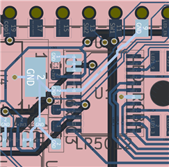
    Here are the schematic and board images. The LP5012 footprint is TSSOP-24. The LEDs are connected in the most convenient way to route the PCB traces; I was intending from the start to use independent control, and not use the RGB banking feature. 

    Here is the full register dump if it is still useful.

    Write value 0x40 (0b01000000)   to register 00h 
    Write value 0x34 (0b00110100)   to register 01h

    Read  value 0x40 (0b01000000) from register 00h
    Read  value 0x34 (0b00110100) from register 01h
    Read  value 0x00 (0b00000000) from register 02h

    Read  value 0xff (0b11111111) from register 03h
    Read  value 0x00 (0b00000000) from register 04h
    Read  value 0x00 (0b00000000) from register 05h
    Read  value 0x00 (0b00000000) from register 06h

    Read  value 0xff (0b11111111) from register 07h
    Read  value 0xff (0b11111111) from register 08h
    Read  value 0xff (0b11111111) from register 09h
    Read  value 0xff (0b11111111) from register 0Ah

    Read  value 0x00 (0b00000000) from register 0Bh
    Read  value 0x00 (0b00000000) from register 0Ch
    Read  value 0x00 (0b00000000) from register 0Dh
    Read  value 0x00 (0b00000000) from register 0Eh
    Read  value 0x00 (0b00000000) from register 0Fh
    Read  value 0x00 (0b00000000) from register 10h

    Read  value 0x00 (0b00000000) from register 11h
    Read  value 0x00 (0b00000000) from register 12h
    Read  value 0x00 (0b00000000) from register 13h
    Read  value 0x00 (0b00000000) from register 14h
    Read  value 0x00 (0b00000000) from register 15h
    Read  value 0x00 (0b00000000) from register 16h
  • Hi Monet, could you keep following this case.

  • Hi Luke,

    There is no problem about the schematic. Please try the following steps.

    1. power on
    2. set LED_EN to high level(using multimeter to make sure that the LED_EN keeps high during operation)
    3. write 0x40 to 00h
    4. write 0x34 to 01h
    5. write 0x0f to 07h
    6. write 0x0f to 0Bh

    please notice that do not perform any read instruction during this operation. watch the LED_EN and VCC voltage.

    Best Regard 

    Monet Xu

  • Hi Monet,

    I haven't forgotten about this, I will attempt this in a few days when I have some time to set up the equipment. Apologies for the delay.

    Thanks, Luke

  • Hi Luke,

    It will be OK, if there is any progress contact me again. I will keep supporting this case.

    Monet Xu

  • If there is no further feedback i will close this thread.

  • I have discovered that pins 1,2,3 on U1 are disconnected from the main ground; the chip still registers as the expected address when probing the I²C bus, but this does mean that AGND is not ideally connected to ground. 

    However, there is no such problem with U2, yet it exhibits the same issue as U1. I will attempt the troubleshooting suggested by Monet on both chips, I apologise again for the delay as due to the design, it is hard to probe the chips while they are in operation, and I do not have a lot of time at the moment. Progress is being made, but slowly, so if it is okay I would like the thread to remain open for the time being

    Thanks again

  • Since the laber day is from 5.1 to 5.5, our expert will reply you on 5.6 

  • Hi Monet

    Apologies for the long delay. I have now had a chance to attempt this.

    LED_EN and VCC stayed at 3.3V before, during, and after the write instructions. By setting my multimeter to "minimum" mode, I can be sure that it never went below 3.3V.

    Thanks, Luke.

  • Hi Monet, please help to keep following this case.