Dear team,
My customer are trying to add series resistor(Red circle) to solve ringing issue. please review below schematic and waveform and let me know your opinion.
1. Will adding series resistor(Red circle) like below cause other side effect?
2. I think the series resistor on VDD and VEE line plays the similar role as Gate Resister. Is it right?
If yes, I think the switching time have to be slow but as you can see below waveform, we can see similar speed under without/with series resistor. please let me know your opinion on this.
3. Is this concept normal or unique concept?
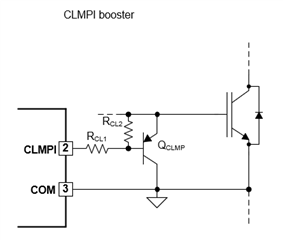
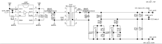
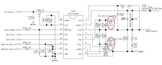
<schematic>
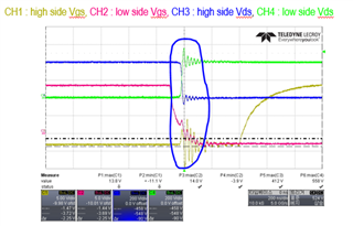
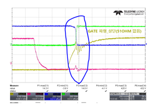
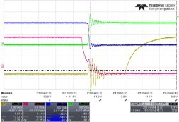
<wave form>
- without series resistor (Yellow Vgs)
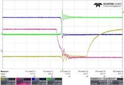
- with series resistor (Yellow Vgs)
Thank you.