This thread has been locked.

If you have a related question, please click the "Ask a related question" button in the top right corner. The newly created question will be automatically linked to this question.

LM46001-Q1: Cboot series resistance limitation

Part Number: LM46001-Q1

Hi Team,

LM46001-Q1 was used on customer side. Now they have a Conduction issue when they passing EMI test.

When they try RC on SW pin, it doesn't improve after try may RC value. But when they try to connect a resistance between Cboot pin and Capacity. It solved conduction issue.

Is there any risk when they connect a 51 ohm resistance between Cboot pin and capacity?

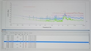
Conduction before add 51 ohm resistance:

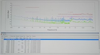
Conduction after add 51 ohm resistance:

Waveform on Cboot(Use differential probe) before add 51ohm resistance:

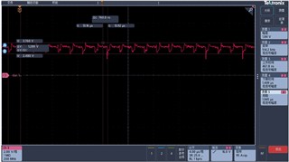
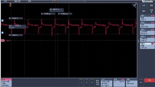
Waveform on Cboot(Use differential probe)after add 51ohm resistance:

Best Regards

Songzhen Guo

  • Songzhen Guo,

    Yes this is a legitimate method of improving EMI called slew rate control. The concern is if the device hits BOOT UVLO. The BOOT voltage is used to turn on the high-side FET. If that voltage is too low, the FET won't turn on properly and may overheat and damage the device, so we implement BOOT UVLO inside the IC to force the SW node low to recharge the BOOT capacitor if the BOOT-SW voltage is below the BOOT UVLO threshold. A BOOT resistor that's too large may hit BOOT UVLO in normal operating conditions which would hinder proper switching.

    I recommend increasing the boot resistor until you see switching issues or an unacceptable amount of heat rise, then don't use a value higher than 1/10th of that value for your final design.

    -Sam