This thread has been locked.

If you have a related question, please click the "Ask a related question" button in the top right corner. The newly created question will be automatically linked to this question.

LM25101: LM25101

Part Number: LM25101
Other Parts Discussed in Thread: UCC27289, SN6501

Hi,

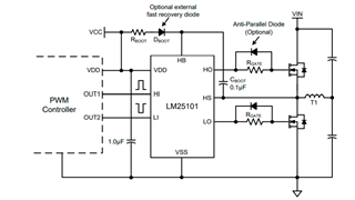
We found there is about 6V on HS when LM25101 is used to driver the high-side and the low-side N-Channel MOSFETs in a synchronous buck. The VDD is 10V.

It can be pulled down to 0.3V with paralleling a 10K on HS to GND.

We removed the MOSFET and the voltage on HS still exists. The leakage current on HS is about 60uA.

Does it be normal? Or how to fix it ?

The same phenomenon is on UCC27289

  • Hello Qu,

    In the case where VDD rises which charges the HB capacitor through the boot diode there is a current path from VDD to HB to charge the boot capacitor. If the HS pin is high resistance even when MOSFETs are connected, the charging current through HB to the HB capacitor will raise the HS pin.

    The HB capacitor is normally charged completely when the LO driver output turns on and the low side FET switches the HS pin to ground. This behavior is expected, and with the MOSFETs removed the HS will not have a path to ground.

    You can try with the MOSFETs connected and apply VDD and the driver inputs to confirm the HS pin switches to ground and the HO output starts working.

    Confirm if this addresses your questions or you can post additional questions on this thread.

    Regards,

  • We removed the boot capacitor but the voltage on HS still exists. Actually, with other passive components removed, there exists voltage on HS with supplying VCC and pulling LI and HI to GND.

    Can you recommend another Half-Bridge Gate Drivers which HS can be 0V when HS pin is in high resistance to GND.

  • Hello Qu,

    I am not aware of any half bridge drivers from TI or any source that will not have the current path from VDD through the boot diode to charge the HB capacitance using a bootstrap floating bias circuit.

    Is the resistance from HS to ground that you confirmed works an option?

    It is not clear why you need a condition where the HS is high impedance in a MOSFET half bridge configuration and you require HS at ground with no low side FET switching. Can you explain why you need this in your application?

    Regards,

  • We removed the the boot capacitor and the boot diode to ensure there is no charging path between VDD and HS, but voltage on HS still exists.

    We are designing a a synchronous buck which output is 0V in disabled. The output is not 0V for HS voltage now.

  • Hello Qu,

    I have not tried removing the HB cap to confirm your findings, but it is not a big surprise. When HB-HS has voltage potential there is an internal quiescent current that flows from HB to HS, which is this floating drivers ground reference. This would also be a path which could raise HS if the resistance is very high.

    As I mentioned before, all floating high side drivers in half bridge drivers will typically use a bootstrap supply and will have some quiescent current flowing in the HB to HS. The only option would be to have a dedicated floating bias such as with the SN6501 transformer driver from TI.

    Is some pull down resistance on HS not an option? Although I see you mention that this is for a sync buck and you want to disable the output, is the output minimum load of the sync buck > 10k Ohms that you mention solves the issue?

    Regards,

  • The output of the sync buck is in open circuit.

    The HS voltage turns to 0.3V when paralleling a 10k between HS and GND.

    It seems the Half-Bridge Gate Drivers cannot ensure the the sync buck's output to 0 when the buck is disabled, right?

  • Hello Qu,

    In your particular case, where it looks like you can have an output load condition that results in a very high resistance on the HS node, it sounds like the IC quiescent currents of the high side driver is something you have to take into consideration.

    We do not hear this type of concerns with sync buck regulators since I think in almost all cases there is likely some resistance on the buck output.

    Regards,

  • TI must be able to provide a sync buck with no voltage on output when the buck is disable and the output is in open circuit.

    It seems the Half-Bridge Gate Drivers cannot achieve it in Half-Bridge Gate Drivers typical application.

  • Hello Qu,

    TI products include quite a number of sync buck solutions with integrated FETs and specific controllers, and drivers targeted for this market.

    These devices, sync buck controllers,  are not in my area of coverage. It is quite possible one of the sync buck solutions addresses the concern you have with the LM25101 driver. 

    Regards,