This thread has been locked.

If you have a related question, please click the "Ask a related question" button in the top right corner. The newly created question will be automatically linked to this question.

UCC28704: UCC28704 used in flyback

Part Number: UCC28704

Hi experts,

The customer has came across the problem that the UCC28704 can't work normally in their flyback circuit.

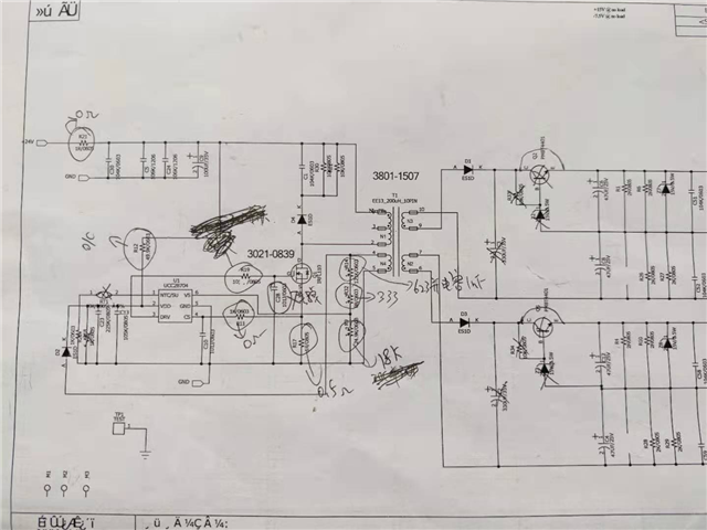
Circuit parameter and test condition:

      1. Vin_flyback= 24V, Vout_flyback = 24V.

      2. Flyback circuit are using IGBT for it's switch mos, Vgs_min= -9V, Vgs_max= 15V.

      3. Dual output and transformer is 100uH, 25:25:25.


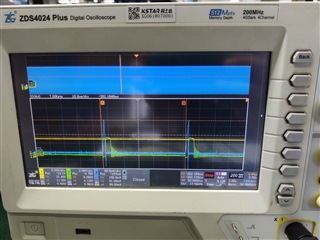
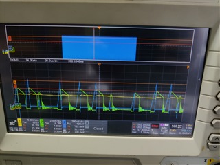
The phenomena is that:

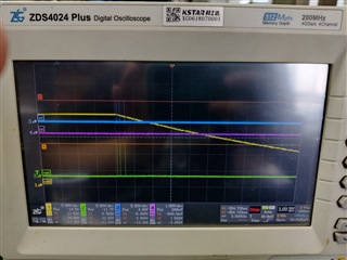
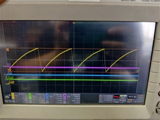
       When flyback is on-power, pin Vdd will drop from 21V to 7.6V, and you can see there is 3 ripples appeared.


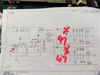
Measured we have tried:

        1. C10 value is changed below 30pF or not used;

        2. R19 = 0Ω;

        3. C28 is not used.

        4. Confirmed the transformer's connection way.

Result:

         Problems not be solved. There still no Vgs for flyback's IGBT.


Next step:

        Maybe the soft start is not be triggered.

Could you help  support  on this topic ? There is a little urgent, thank you.

  • Hi Rachel,

    Three consecutive pulses after VDD reaches to 21V, then VDD UVLO restart means a protection has been detected .

    from your schematic , looks like the transformer polarity is wrong connected , if so , it will trigger primary Over-current protection.

    The total resistor on NTC pin should be higher than 9.05k , but looks like you used a 10k NTC + 1k fixed resistor on NTC , could you please increase NTC resistor

    All of protections are listed in datasheet section 7.3.7. if above two items have not solved you issue , please check the protection on 7.3.7 one by one.

    Thanks.

  • Hi Jaden,

    Thank you for your reply.

    customer has solved start-up problem. They changed the values as below.

    But there is a small value on Vs, and the MOS is in constant current zone.

    Could you help solve it?

    Thank you.

  • Hi Rachel,

    Could you please clarify or give more details description  what the mean of "But there is a small value on Vs, and the MOS is in constant current zone"  and please ask customer to share clean schematic .

    Thanks.

  • Hi Jaden,

    Thank you for your reply.

    The methods you provided and feedback:

    1. Transformer polarity is wrong connected -> Setting right, confirmed by customer.

    2. The total resistor on NTC pin should be higher than 9.05k -> Raised to customer, but no feedback yet.

    Newest waveforms:

        ch2 Vs sampling voltage;
        ch3 Cs sampling voltage.


       Pic 1( No load)


        Pic2 (load= 2W)

     Suggestion from myside:

        1. Rs1=68k, Rs2=13.845k;

        2. C10< 30pF;

        3. R19=0.


    Are you free tomorrow? I want to have a F-F discussion with you.

    Thank you.