This thread has been locked.

If you have a related question, please click the "Ask a related question" button in the top right corner. The newly created question will be automatically linked to this question.

UCC12050: EMI problem

Part Number: UCC12050
Other Parts Discussed in Thread: UCC12040, ,

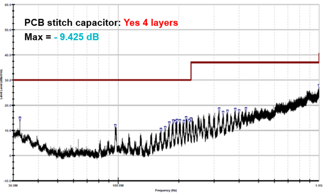
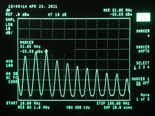
Unfortunately, we have noticed high EMI with our new PCB. The UCC12050 isolates +5V from USB to other circuitry, and part of the EMI passes to the USB cable. Additional filtering here might help, but a near field probe shows a number of harmonics at both sides of UCC12040:

What can be done to improve the design? The layout is very similar to UCC12050EVM-022, with bypass caps close to UCC12050 pins to minimize loops. Initial idea was that different ground planes might act as an antenna, but that appears to be a false assumption.

  • Hi Petri

    You mentioned you are measuring using a near field probe and it seems to do a good job capturing the harmonics which are happening at n*8MHz. This approach is good for a first pass at pre-compliance screening but you are only detecting peaks due to magnetic filed emissions and not capturing the E Field contribution. Have you received the UCC12050EVM-022 and tried to measure the near field probe emissions compared to what you are seeing with your system? An A vs B comparison would be good to have as a measure of what your system might be contributing (specifically the USB cable). As a next step, have you tried running a CE scan? The UCC12050EVM-022 passes CISPR 32, class B with no EMI filter components and is shown below:

    Regards,

    Steve M

  • Thank you for your reply. No, I do not have UCC12050EVM-022 at hand, but I will get one for reference. I don't have a proper commercial E-field probe at the shop, but the one I have seems not to be picking strong signals. Interestingly, both E and H probes show the highest peak at ~32 MHz and not 8 MHz as I was expecting to. Also, harmonics can be found from surprisingly high signals too, like up to 200 MHz range. This is confirmed by the EMC lab, which detected the same peaks exceeding the EN55032B limits.

    There is no interlayer stitching capacitor, but it wouldn't be hard to make by using a 4-layer PCB. However, while trying to mitigate the problem, I placed different caps from 100 pF to 100 nF between the GNDP and GNDS with no difference in H-field at least while probing. I am unsure if this applies as a valid test for lack of interlayer stitching cap.

  • Petri,

    The interlayer PCB stitch capacitor is only going to provide common mode (CM) capacitance in the range of 10-20pF. The fact that you applied a physical capacitor in the range of 100pF<C<100nF and saw no difference is concerning. This tells me the CM path is stronger somewhere else in your circuit because you applied the mitigation directly at the source of what you believe to be the culprit and saw no change. Or perhaps your measuring technique is questionable or maybe the USB cable? You need to measure an d compare to the EVM I mentioned previously and also run a complete CE scan using the proper set up for whatever EMC standard you are hoping to pass. Even in the EMI scan I provided in my response, you can see measured harmonics within the region you mentioned but they are well below the CISPR 32, class B limit. Is there data transfer and power through the USB cable when you are making near field measurements? Can you remove the cable and apply a 5V battery into the UCC12050 input to baseline the effect of the cable?

    Steve M