This thread has been locked.

If you have a related question, please click the "Ask a related question" button in the top right corner. The newly created question will be automatically linked to this question.

TPS2115A: Redundant 5V supply via 5VUSB and external +5V from regulator

Part Number: TPS2115A
Other Parts Discussed in Thread: TPS2121, , TPS2115, TPS2116, TPS2113A, TPS2120

Hi,

Our project decided to use TPS2121 for Power MUXing two 5V sources for redundancy. However, due to the situations all around the world, TPS2121 has been out of stock and production of our PCB boards have been suspended. We checked on the schedule for restocking but the dates are off our target schedules. Therefore, we decided to instead use TPS2115ADRB. 

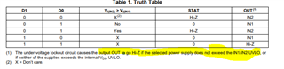
We decided to let an external 5V be connected to IN2 and a 5VUSB to IN1. We designed it such that, by default, the 5V supply comes from the external 5V supply and switches to 5VUSB in case the external 5V drops. Then I decided to use the STAT pin to drive an LED to turn on when the Output 5V is supplied by the 5VUSB instead of the default 5V external.

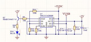
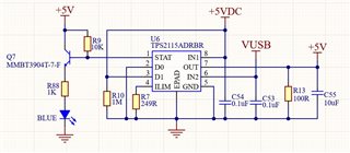
I am attaching here the screenshot of the sample schematic for using the TPS2115A.

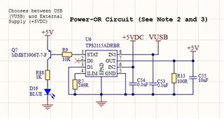
I just would like to confirm if this design will work according to what we have in mind. BTW, I am operating the TPS2115 in autoselect mode. +5VDC comes from a 5V regulator IC, VUSB is the 5VUSB, and +5V is the output of the TPS2115ADRB.

Any suggestions are also welcome. Thanks.

  • Hi Ramon,

    This setup will work as intended but please note that TPS2115A is not capable of performing faster switchover like that possible with TPS2121.

    We do offer TPS2116 which can switch faster than TPS2115A and is similar to TPS2121 but it does not allow for a user set current limit. I encourage you to take a look at this newer device as well. 

    Do note that in this mode of operation, when both inputs are 5V there is a chance that the device could switch back and forth between the inputs as there is no priority set. TPS2116 allows for the user to set priority.

    Thanks,

    Shreyas

  • Hi Shreyas,

    Thank you for these information. I checked the TPS2116 and it looks good for this application, however, it is still non-stocked with the distributors, so I am still leaning towards using TPS2115A.

    Instead of the initial configuration, I decided to use the manual selection mode, in which the D0 is connected to GND and I decided to connect D1 through a voltage divider to IN1. It works such that, when 5V external is connected at IN1, the voltage divider supplies 2.5V at D1 and so IN1 is selected using the manual mode. When IN1 is not present or IN1 falls below 4V (D1 < 2V, D1 = logic 0 based on datasheet), D1=0, D=0 indicates that IN2 will be chosen in which STAT will output a logic 0, turning ON the PNP and turns the LED ON to indicate that IN2 is being used as 5V output.

    I am attaching the schematic snapshot here. Can you confirm that this will work as mentioned above?

    Thanks again and suggestions are welcome.

    Ramon

  • Hi Ramon,

    Your new setup looks to be automatic switchover and not manual switchover. This will work but it is not ideal as there is a wide voltage window between high and low on the Dx pins. 

    The TPS211xA PowerMUXes are a family and we actually have a very similar device in TPS2113A. This device is built for this resistor divider control methodology from one of the voltage rails. With the Vsns pin (instead of the Dx pins) you get a tighter control and priority setting. Since you are still in your design phase, I would also recommend you to take a look at TPS2113A as this device is the auto switching variant of TPS2115A.

    Thanks,

    Shreyas

  • Hi Shreyas,

    Thanks for this. The problem is from the TPS211x family, TPS2115A is the only available part with stocks on distributors. TPS2121 is also out-of-stock and as much as possible would not like to work with BGA in the moment  with TPS2120. Can you suggest other parts possible if any?

    Many thanks,

    Ramon

  • If I decided to use TPS2115A in manual mode, will this work? Also using the STAT pin to drive the LED ON when IN2 is used and LED OFF when IN1 is used?

    Thanks,

    Ramon

  • Hi Ramon,

    To start off, using the STAT pin to drive the LED should be acceptable. The STAT pin is a simple open-drain pin. It is not meant to handle huge current or anything like that but it should be able to pull the base of a BJT low. This should not be an issue.

    This setup is will face the same limitation that the resistor divider setup does. In the ideal situation, yes this setup will work as you expect with the device selecting IN1 when it becomes valid. But the true behavior may be heavily dependant on the slew rate of the 5VDC rail. As the voltage becomes valid there is a chance that D1 goes high before IN1 rises up:

    This is because between the 0.7V and 2V levels, the behavior of the device is not defined so some devices may assert high early and some may not. Lets assume the situation where D1 asserts high at 1.2V. In this case, IN1 is still under UV but D1 is high and so the output could go to high-Z.

    Is there any way you can control D1 externally?

    Thanks,

    Shreyas