This thread has been locked.

If you have a related question, please click the "Ask a related question" button in the top right corner. The newly created question will be automatically linked to this question.

BQ76200: BQ76200, Reverse current protecting

Part Number: BQ76200
Other Parts Discussed in Thread: BQ78350, , BQ76930

Hello

We are developing a battery pack for e-bikes.
Our problem is reverse current.
The ic we use is as follows.
We developed the product using BQ76930 + BQ78350 + BQ76200.

Our FET circuit diagram is as follows.

https://drive.google.com/file/d/1OECMG2Z0VyjeFhBfp6cE12HQRdz6l6iY/view?usp=sharing

Our maximum output is 120A.
The motor is using a 5KW motor.
The reverse current from the motor is very large.

While we were testing, the following problems occurred.
1. TVS Diode exploded.
2. TVS Diode shorted, Varistors also caught fire.
3. Overvoltage cut-off occurs because of reverse current.
4. Resistance 120 ohms burns out of CAN communication components. Because of this, the charger is broken and the battery is broken.

We need to solve the reverse current coming in from the motor.
Ignorant question, but is it possible to charge it if I apply a circuit that prevents reverse current?

I would like to ask for your help on what part of our circuit we need to modify.

  • Hi Dongwoo,

    If I understand correctly when the motor acts as a generator it creates a high voltage and pushes a lot of current back into the battery as a charge current.  The battery is not able to take the current or over time it charges sufficiently that the cell voltages rise and the charge path turns off allowing the voltage to rise on the PACK+.  The TVS and varistors are damaged.  

    Current should flow in or out of the battery as needed.  If current exceeds the OCC threshold set in the BQ78350 it will turn off the charge FETs allowing the voltage to rise on the motor and showing up on the PACK+ affecting the TVS, Varistors, and the DSG and PACK pins of the BQ76200.  The charge FETs should withstand the voltage up to their limit, the discharge FETs should be riding with the PACK+.  If the voltage is high enough the TVS will conduct and try to carry the current required, too much power and it will fail as you describe.  The varistors are likely the same.  If the voltage rises sufficiently it will break the BQ76200 since it has a 100V limit.  If the BQ76200 breaks the FETs may then break.

    From a system standpoint charging from the motor as regenerative braking is good when the battery is partly discharged.  Once the battery is full that energy must go somewhere, perhaps you can switch it into some load to prevent it from breaking your components.  You may want to discuss the situation with the motor supplier for techniques suitable with the motor.  From the battery standpoint the electronics need to shunt the current within their power handling capability or allow a higher voltage.  The BQ76200 has the 100V voltage limit, so it may not be suitable if the voltage must be allowed to go higher.  

    If you have a system which prevents reverse current it will not allow charge in that path.  Some of this type system uses ideal diodes, basically FETs which can be enhanced when the current is flowing through the diode.  When the current tries to flow in the reverse direction the FET turns off and the FET diode and sensing electronics must withstand the voltage applied.  Some systems design separate charge and discharge paths. The BQ78350 has a body diode protection feature which can not be turned off, so it does not always work well in those systems when charger and load can both be attached. Also the separate charge and discharge path systems have the concern of blocking charge through the discharge path and blocking discharge through the charge path.

  • Thank you for answer.
    So, what should I do?

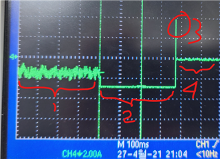
    The figure below shows the situation where Over Current occurs.

    We have to solve this problem.
    Take a look at my circuit and ask for your advice.
    Thank you.

    https://drive.google.com/file/d/1Ofw9H-8jn1Bzyr604wSFLvpLH_51NaVA/view?usp=sharing

  • HI Dongwoo,

    I don't fully understand your waveform.  One interpretation may be:

    Region 1 seems to be a varying current.

    Region 2 has limited, the 370 ms duration fits with what could be detected by the BQ76930, it will give a reading every 250 ms so delay from an input may be up to 500 ms. 

    Region 3 may be an inductive response from the system or from the scope interpreting samples.

    Region 4 appears to be off without failure.

    It is not clear to me why the current would be so stable during region 2.  Perhaps it is a stable forced test current. If it comes from the motor it would seem it may vary .  Once the BQ78350 turns off the charge FET the motor may generate a high voltage which could break things.  The voltage won't be shown in the current waveform for the cells, but may show in the current from the motor if that flows into the failed components.

    Protection components would need to survive the power and voltage provided during the region 3 and region 4.  The BQ76200 can only take 100V, other components must limit the transient voltage or switch off the circuit which would be unusual.

    I don't know your ebike architecture. Would it have some dynamic braking system which would absorb energy provided by the motor if the battery protected?  This might limit the voltage to the battery to prevent the components from breaking.